AL802ULADAJ Installation Guide - 7 -
Terminal Identification Table:
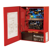
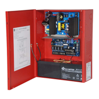
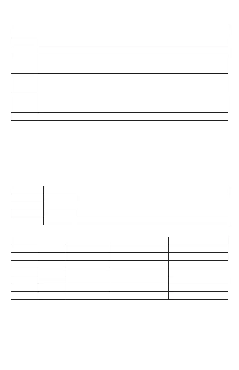
AL800ADA Power Supply Board*
Terminal
Legend
Function/Description
L, G, N Connect 120VAC to these terminals: L to hot, N to neutral.
– DC + 24VDC @ 8A in alarm non power-limited output.
AC FAIL
NO, C, NC
Form “C” dry contacts used to instantaneously signal the loss AC to local annunciation devices,
with AC present terminals marked NO and C are open, NC and C are closed. When loss of AC occurs
terminals marked NO and C are closed, NC and C are open.
AC LOCAL
NC, NO, C
Form “C” dry contacts used to instantaneously signal the loss AC to local annunciation devices,
with AC present terminals marked NO and C are open, NC and C are closed. When loss of AC
occurs terminals marked NO and C are closed, NC and C are open.
BAT FAIL
NO, C, NC
Form “C” dry contacts used to signal low battery voltage or loss of battery voltage.
Under normal conditions terminals marked NO and C are open, NC and C are closed. During a
trouble condition terminals marked NO and C are closed, and NC and C are open (Fig. 2, pg. 9).
+ BAT – Stand-by battery input (leads provided) (Fig. 2, pg. 9).
*Power Board Parameter Specifications:
• AC Fail condition will report approximately 30 seconds after loss of AC. To delay report for 2.5 to 3 hours
cut jumper AC DELAY on the Power Supply Board (AC trouble output delay option). If this mode is
selected the Power Supply Board must be reset by removing all power to it for 30 seconds.
• Low battery condition will report at approximately 21VDC.
• Battery presence detection will report within 180 seconds after battery remains undetected (missing or
removed). A restored battery will report within 30 seconds.
LED Diagnostics:
AL800ADA - Power Supply Board
Red (DC) Green (AC) Power Supply Status
ON ON Normal operating condition.
ON OFF Loss of AC. Stand-by battery is supplying power.
OFF ON No DC output.
OFF OFF Loss of AC. Discharged or no stand-by battery. No DC output.
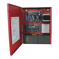
AL800LGK9E - Logic Board
LED OFF ON BLINK (LONG)* BLINK (SHORT)**
Output 1 Normal Alarm Condition Trouble Condition Trouble Condition Memory
Output 2 Normal Alarm Condition Trouble Condition Trouble Condition Memory
Output 3 Normal Alarm Condition Trouble Condition Trouble Condition Memory
Output 4 Normal Alarm Condition Trouble Condition Trouble Condition Memory
Input 1 Normal Alarm Condition Trouble Condition –
Input 2 Normal Alarm Condition Trouble Condition –
Fault Normal Alarm Condition – –
* Indicates current trouble condition. When trouble (open, short or ground) occurs on a specific output, the
corresponding red output LED, [OUT1-OUT4] will blink. The corresponding green input LED will
blink as well. Loop trouble will report within 30 seconds.
** Indicates trouble condition memory. When a trouble condition restores, the units red output LED,
[OUT1-OUT4] will blink with a shorter and distinctly a different duration.
The green input LEDs will be off (normal condition).
To reset the memory depress the reset button (Fig. 2c, pg. 9). The LED(s) will extinguish.
Note: If indicating circuits have been restored, memory reset is not required for normal operation of the unit.
 Loading...