AL802ULADAJ Installation Guide - 9 -
SW1
-- DC +
SW2
+ OUT1 --
OUT1 OUT2 OUT3 OUT4
INP1 INP2
FAULT
NC CNOC "FAULT" NC
OUT1 OUT3
OUT2 OUT4
INPUT SELECT
TEMPORAL
STROBE SYNC
IN > OUT SYNC
IN1+
IN1--
IN2--
IN2+
C "DRY1" NC
RET1+
RET1--
RET2--
RET2+
C "DRY2" NC
+ OUT2 --
+ OUT3 --
+ OUT4 --
INPUT SELECT
TEMPORAL
STROBE SYNC
IN > OUT SYNC
-- AUX +
UPPER TERMINALS
LOWER TERMINALS
Addressable
Control Module
Trigger Output
Non-Supervised
Class E
line
neutral
Green Lead
Divider
Use separate
knockout.
Keep 0.25"
spacing from
non power-
limited wiring
Regulated
Power-Limited
NAC Outputs
2.5A max. per
output in alarm.
Total = 8A.
(Supervised)
RESET
Unswitched
120VAC
power mains
(non power-
limited)
Non power-limited
Supervised
Non power-limited
5A
250V
ON
1
ON
1
Compatible Special
Application Devices.
See Compatibility List
Non-Supervised
Class E
AC Local
power-limited
This connection is used to
monitor AC and Bat Fail and
will cause a simultaneous trouble
condition to the FACP's IN1 and IN2
Non-Supervised Class E
Supervised
Power-Limited
Common trouble output to Digital Communicator
or Local Annunciator Dry output Contact
(Form "C" contacts) Non-Supervised Class E.
Connection to triggering devices must be made
within 20 ft. of distance and using conduit for wiring.
Input Fuse
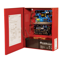
Fig. 2a
SW1
-- DC +
SW2
+ OUT1 --
OUT1 OUT2 OUT3 OUT4
INP1 INP2
FAULT
NC CNOC "FAULT" NC
OUT1 OUT3
OUT2 OUT4
INPUT SELECT
TEMPORAL
STROBE SYNC
IN > OUT SYNC
IN1+
IN1--
IN2--
IN2+
C "DRY1" NC
RET1+
RET1--
RET2--
RET2+
C "DRY2" NC
+ OUT2 --
+ OUT3 --
+ OUT4 --
INPUT SELECT
TEMPORAL
STROBE SYNC
IN > OUT SYNC
-- AUX +
UPPER TERMINALS
LOWER TERMINALS
Addressable
Control Module
Trigger Output
Non-Supervised
Class E
line
neutral
Green Lead
Divider
Use separate
knockout.
Keep 0.25"
spacing from
non power-
limited wiring
Regulated
Power-Limited
NAC Outputs
2.5A max. per
output in alarm.
Total = 8A.
(Supervised)
RESET
Unswitched
120VAC
power mains
(non power-
limited)
Non power-limited
Supervised
Non power-limited
5A
250V
ON
1
ON
1
Compatible Special
Application Devices.
See Compatibility List
Non-Supervised
Class E
AC Local
power-limited
This connection is used to
monitor AC and Bat Fail and
will cause a simultaneous trouble
condition to the FACP's IN1 and IN2
Non-Supervised Class E
Supervised
Power-Limited
Common trouble output to Digital Communicator
or Local Annunciator Dry output Contact
(Form "C" contacts) Non-Supervised Class E.
Connection to triggering devices must be made
within 20 ft. of distance and using conduit for wiring.
Input Fuse
SW1
-- DC +
SW2
+ OUT1 --
OUT1
OUT2
OUT3
OUT4
INP1 INP2
FAULT
NC CNOC "FAULT" NC
OUT1 OUT3
OUT2 OUT4
INPUT SELECT
TEMPORAL
STROBE SYNC
IN > OUT SYNC
IN1+
IN1--
IN2--
IN2+
C "DRY1" NC
RET1+
RET1--
RET2--
RET2+
C "DRY2" NC
+ OUT2 --
+ OUT3 --
+ OUT4 --
INPUT SELECT
TEMPORAL
STROBE SYNC
IN > OUT SYNC
-- AUX +
UPPER TERMINALS
LOWER TERMINALS
Addressable
Control Module
Trigger Output
Non-Supervised
Class E
line
neutral
Green Lead
Divider
Use separate
knockout.
Keep 0.25"
spacing from
non power-
limited wiring
Regulated
Power-Limited
NAC Outputs
2.5A max. per
output in alarm.
Total = 8A.
(Supervised)
RESET
Unswitched
120VAC
power mains
(non power-
limited)
Non power-limited
Supervised
Non power-limited
5A
250V
ON
1
ON
1
Compatible Special
Application Devices.
See Compatibility List
Non-Supervised
Class E
AC Local
power-limited
This connection is used to
monitor AC and Bat Fail and
will cause a simultaneous trouble
condition to the FACP's IN1 and IN2
Non-Supervised Class E
Supervised
Power-Limited
Common trouble output to Digital Communicator
or Local Annunciator Dry output Contact
(Form "C" contacts) Non-Supervised Class E.
Connection to triggering devices must be made
within 20 ft. of distance and using conduit for wiring.
Input Fuse
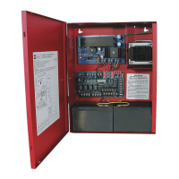
Fig. 2b
Common trouble
Input/Output
Fig. 2c
Trouble Memory Reset Button
Hookup Diagram:
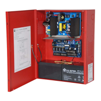
Fig. 2
 Loading...