APPENDIX B. ELECTRICAL AND DATA CONNECTIONS
IS-300CA INVERTER POWER SUPPLY
990-418 B-15
Pin No. Name
EtherNet/IP
TM
model
Description
32
OUT5 YES
33
OUT COM
Common pin for output pins. This pin is the common pin for the NG,
CAUTION, END, COUNT ERROR, READY, STEP END, and WELD
ON pins.
34
SOL POWER
Power input pins to drive the solenoid valve.
Input 120
V AC or 24
V AC/DC power.
35
SOL COM COM pin for the solenoid valve.
36
37
SOL 1
SOL 2
Solenoid valve output pins. 36: SOL1; 37: SOL2
These pins are closed for the duration of the 2ND STAGE input.
Output between SQD and HOLD.
When the off time (OFF) is set, this pin is output between SQZ and
HOLD after the second sequence.
The contacts are rated at 120
V AC or 24
V AC/DC at 0.5
A
(semiconductor switches).
Use a solenoid valve with a current capacity ≤ 0.5A.
38
*2
39
*2
VOLT SENS
Secondary voltage input pins.
Connect to the electrodes of the welding head during constant-power
or constant-voltage control or when monitoring the secondary voltage.
*1
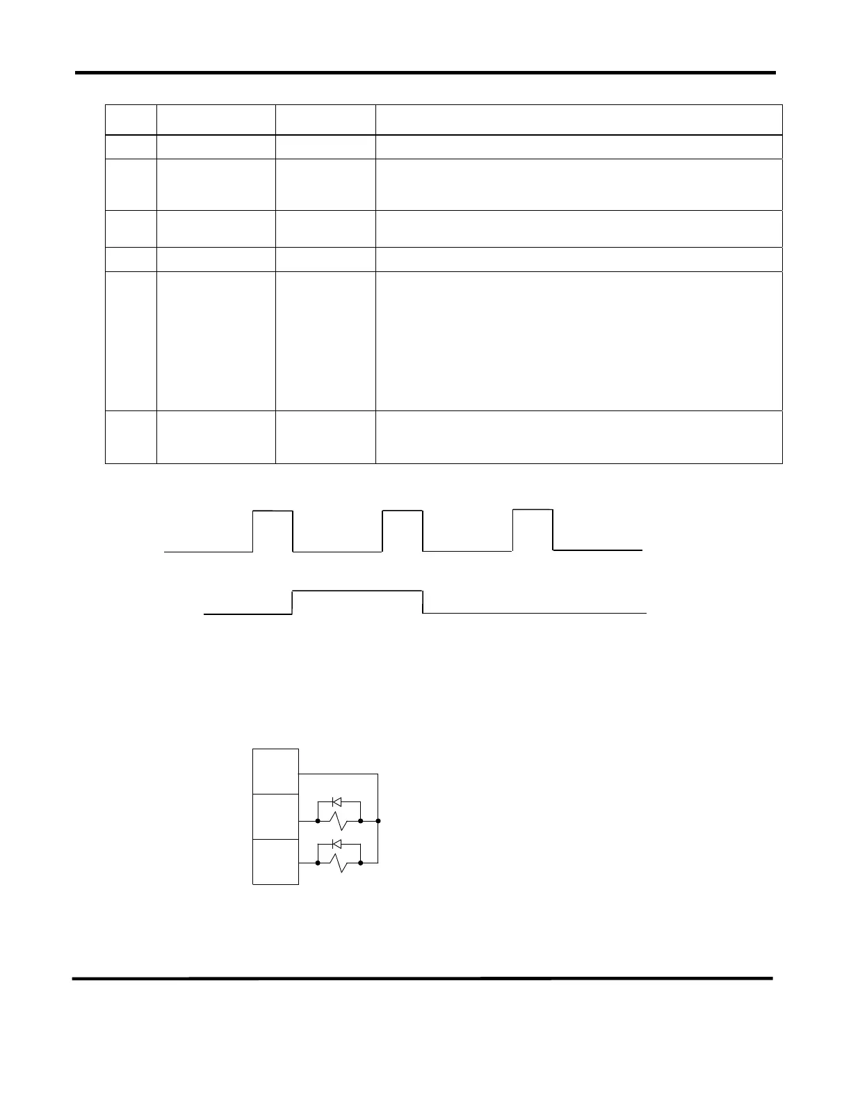
*2 When using 24
V DC solenoid, install diodes on measures to prevent surge voltage.
Example; when inputting + to Pin 34 and – to Pin 35.
When the sequence is stopped at (A), error (CAUTION) is not
displayed. It’s because the contents when stopped is displayed on the
program unit.
OFF
OFF
GOOD
GOOD
CAUTION
(A)
CAUTION
+ -
+-
35
36
37


 To Next Page
 Loading...
