Do you have a question about the Amana AVH09 and is the answer not in the manual?
Details on wire size, fuse/breaker, grounding, and wire sizing specifications.
Recommended branch circuit sizes and AWG wire gauges for different amperage ratings.
Table showing indoor airflow (CFM) based on fan speed and external static pressure.
Specifies minimum clearances for outdoor installation, side-by-side, and grouped units.
Guidelines for proper spacing from the VTAC exterior louvered grill for obstructions.
Table of chassis and rough opening dimensions for AVH09, AVH12, AVH18, and AVH24 models.
Specifies the exact rough opening size required for the exterior wall adapter installation.
Diagram and dimensions for closet installation from the front, showing required clearances.
Diagram and dimensions for closet installation from the left, showing required clearances.
Diagram and dimensions for closet installation from the right, showing required clearances.
Instructions for preparing and fitting the external part of the wall adapter into the rough opening.
Instructions for installing the architectural louver prior to the wall adapter assembly.
Procedure for cutting and removing a section of the plenum gasket for drain pan mounting.
Steps for applying sealant and positioning the drain pan against the plenum flange.
Instructions for attaching the drain pan to the closet floor using pre-drilled mounting holes.
How to plug the unused drain connection ports on the drain pan.
Guidelines for designing the supply duct system using recognized methods and friction rates.
Steps for inserting the unit chassis into the wall adapter and ensuring seal contact.
Connecting a single-stage heat/cool wall-mounted thermostat to the VTAC unit.
Connecting an external switch for controlling unit power from a central desk.
Operation of the chassis's "intake" system for delivering outdoor air via a slide mechanism.
How thermistor feedback prevents compressor operation at low suction temperatures.
Unit's automatic response to prevent indoor room freezing by cycling high fan and electric heat.
Steps for making final ductwork and electrical connections before operating the chassis.
Instructions for replacing the air filter to maintain efficiency and prevent coil damage.
Step-by-step guide to safely disconnect and remove the unit chassis from its installation.
How to access, view, and clear error codes displayed on the VTAC unit's control panel.
Explanation of the unit control panel display, including error codes, history, and maintenance indicators.
A comprehensive table listing all error codes, their associated problems, and recommended actions.
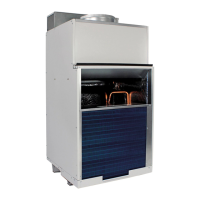
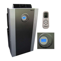
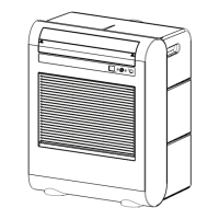
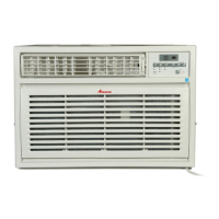
This document describes the VTAC Single Package Vertical Air Conditioning System (AVH 9,000-24,000 Btu/hr), an air conditioning unit designed for vertical installation. It serves as both an installation instruction and owner's manual, emphasizing safety, proper installation, and routine maintenance for optimal performance and longevity.
The VTAC system is a single-package vertical air conditioning unit primarily designed for cooling and heating residential or commercial spaces. It is capable of delivering between 9,000 and 24,000 Btu/hr, making it suitable for various room sizes and climate control needs. The unit is designed for installation on an outside wall, with options for different wall adapter depths to accommodate various wall thicknesses. It features a fresh air door, allowing for the intake of up to 60 CFM of outdoor air, contributing to improved indoor air quality. The system can be controlled via a remote wall-mounted thermostat, offering flexibility in operation modes (single-stage heat/cool, auto, or manual changeover). Additionally, it includes provisions for connection to an external switch, such as a central desk control system door switch, to control power to the unit. The VTAC also has the capability to control a 24VAC relay to activate an auxiliary or transfer fan.
Dimensions and Clearances:
Electrical Data:
Supply Air Flow Data (Indoor CFM & External Static Pressure):
Control Interface Definition:
Maximum Wire Length for Desk Control Switch:
Filters:
Installation:
Operation:
Electronic Control Error Code Diagnostics and Test Mode:
Routine Maintenance:
Servicing / Chassis Quick Changeouts:
Warranty:
Safety Precautions:
| Brand | Amana |
|---|---|
| Model | AVH09 |
| Category | Air Conditioner |
| Language | English |