Component Testing Procedures
!
WARNING
To avoid risk of electrical shock, personal injury or death, disconnect power to oven and discharge capacitor
before servicing, unless testing requires power.
16027356 July 2006
Replaces 16026912
©2006 Maytag Services
4
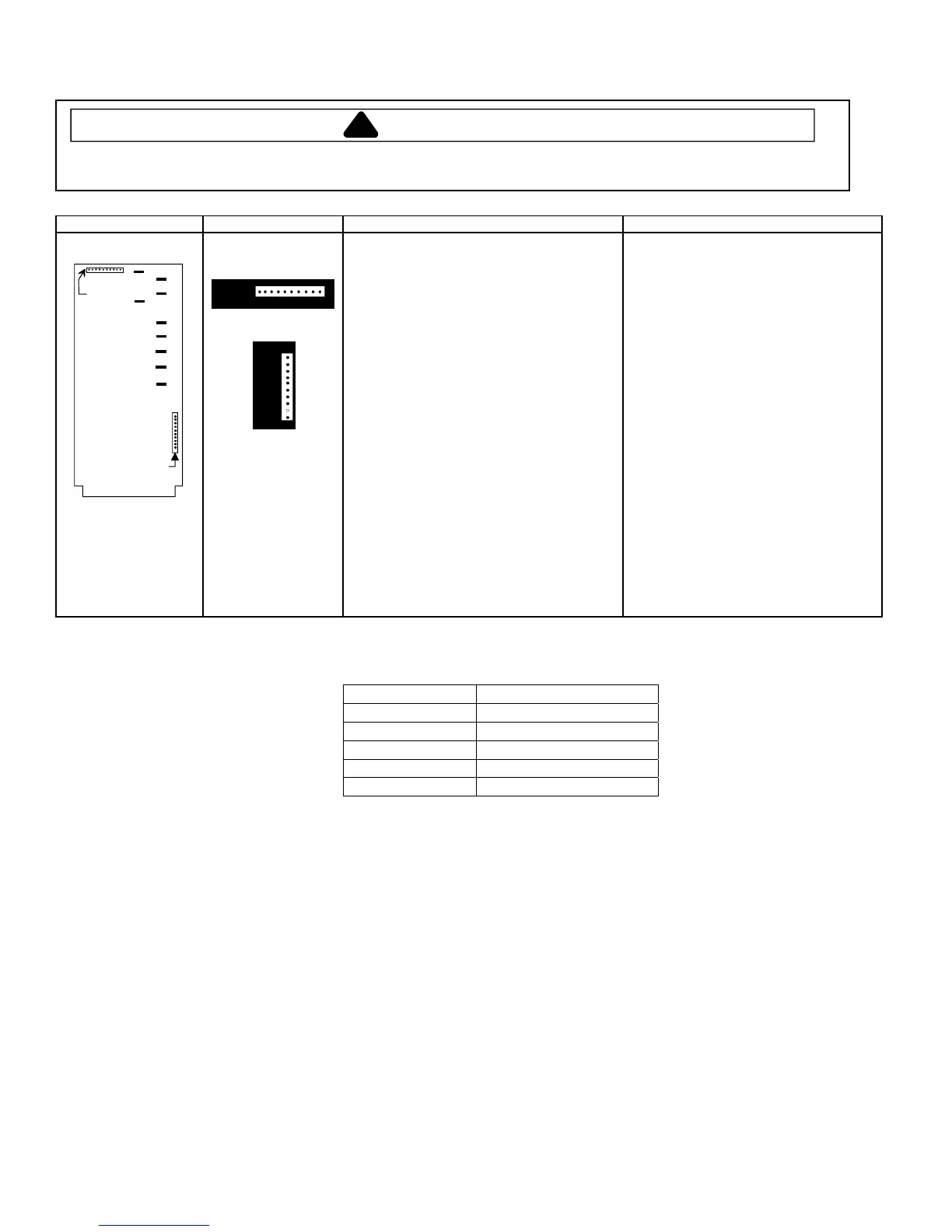
Illustration Component Test Results
Pin #1
Pin #1
P1
P2
A
B
C
D
E
F
G
L
H
Controller board
P2
1
10
P1
1
10
P1 connector used
for touch panel
ribbon
All Models
Line voltage to control board
P2 connector
Pin 1—Pin 3..............................................
Output drive voltage to triac
Triac terminals............................................
Gate—T1..................................................
208 VAC line voltage
Fan relay (controls blower motor, antenna
motor(s), and oven light)
Control board..............................................
Terminals C—D ........................................
Line voltage sensing relay (automatically
switches for 208 or 230 VAC operation)
Control board..............................................
Terminals F—G ........................................
230 VAC line voltage
Fan relay (controls blower motor, antenna
motor(s), and oven light)
Control board..............................................
Terminals C—E ........................................
Line voltage sensing relay (automatically
switches for 208 or 230 VAC operation)
Control board..............................................
Terminals F—H ........................................
Line voltage (All Conditions)
0 VAC (Idle and Standby)
0.9 VAC (Cook)
Line voltage (Idle)
0 VAC (Standby and Cook)
Line voltage (Idle)
0 volts (Standby and Cook)
Line voltage (Idle)
0 VAC (Standby and Cook)
Line voltage (Idle)
0 volts (Standby and Cook)
Error Code Table
Error Code Corrective Action
F1 Replace HV/LV Board
F2 Replace HV/LV Board
F3 Replace HV/LV Board
F4 Replace Touch Panel
F5 Replace HV/LV Board
Conditions
Initial Power Up Condition: Apply power to oven with door closed.
Idle Condition: Oven plugged in, display blank (no other components operating).
Standby Condition: Open oven door, light and motors operate.
Cook Condition: Food load in oven, cook cycle initiated.
 Loading...