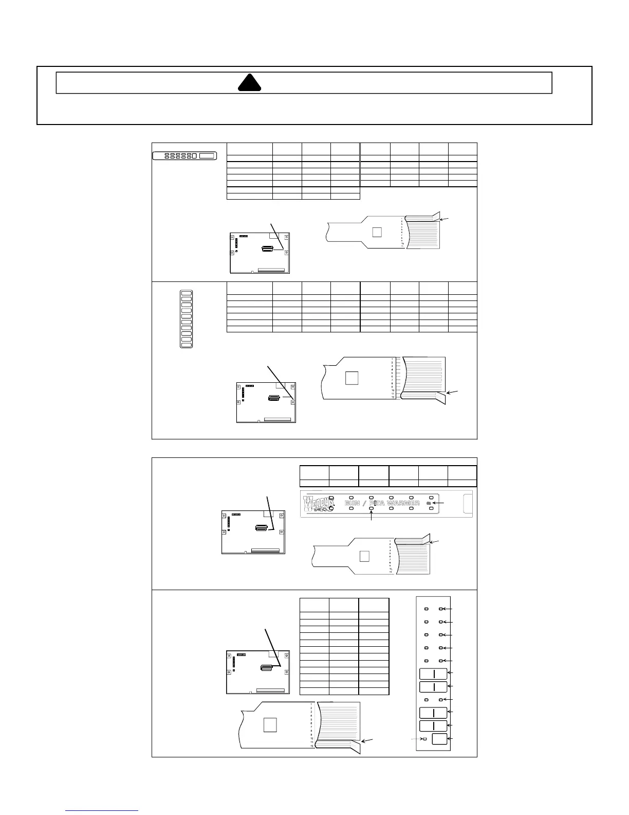
Component Testing Procedures
WARNING
To avoid risk of electrical shock, personal injury, or death, disconnect power to oven and discharge capacitor
before servicing, unless testing requires it.
RS2220001 Rev. 2 20
All models except WDYRC
Top Keypad
Keypad Switch
Ribbon
Trace
Ribbon
Trace
Keypad Switch
Ribbon
Trace
Ribbon
Trace
Menu 4/Quantity S1 11 10 Power Level S19 9 5
To test keypad for proper Menu 3 S3 11 8 Time Entry S22 8 7
operation: Pause S13 10 5 Hold S27 7 6
1. Identify ribbon traces Delete S14 10 4 Enable S28 7 5
for selected keypad Status S15 10 3 Add S36 4 3
using chart. Menu 1 S16 9 8
2. Resistance between Menu 2 S17 9 7
selected traces =
0 ohms.
J4 - Place split in
ribbon cable to
3. Pressing keypad, the right as facing
resistance between the front of the unit.
selected traces is
less than 60 ohms.
Ribbon Cable
L.V. Board
Side Keyboard
Keypad Switch
Ribbon
Trace
Ribbon
Trace
Keypad Switch
Ribbon
Trace
Ribbon
Trace
Stop/Reset S18 3 4 7 S39 6 10
0 S25 4 5 4 S40 7 8
Start S30 4 10 5 S42 7 10
8 S31 5 6 2 S43 8 9
9 S35 5 10 3 S44 8 10
6 S36 6 7 1 S45 9 10
J3 - Place split in
ribbon cable to
To test keypad for proper the right as
operation: facing the front
1. Identify ribbon traces of the unit.
for selected keypad
using chart.
2. Resistance between
selected traces =
0 ohms.
3. Pressing keypad, Ribbon Cable
resistance between
selected traces is
less than 60 ohms.
L.V. Board
Split
1
1
1
J1
J2
J3
J4
J5
1
1
1
1
1
J1
J2
J3
J4
J5
1
1
Split
WDYRC
Top Keypad
J4 - Place split in
ribbon cable to
Switch
Ribbon
Trace
Ribbon
Trace
Switch
Ribbon
Trace
Ribbon
Trace
the right as T-1 10 4 T-2 8 7
To test keypad for proper facing the front
operation: of the unit.
1. Identify ribbon traces
for selected keypad
using chart.
2. Resistance between
selected traces =
0 ohms.
3. Pressing keypad,
resistance betw een
selected traces is L.V. Board
less than 40 ohms.
Ribbon Cable
Side Keypad
J3 - Place split in
ribbon cable to
Switch
Ribbon
Trace
Ribbon
Trace
the right as S1 9 10
facing the front S2 8 9
of the unit. S3 8 10
S4 7 8
S5 7 10
To test keypad for proper S6 6 7
operation: S7 6 10
1. Identify ribbon traces S8 5 6
for selected keypad S9 5 10
using chart. S10 4 5
2. Resistance betw een S11 4 10
selected traces = S12 3 4
0 ohms. L.V. Board
3. Pressing keypad,
resistance betw een
selected traces is
less than 40 ohms.
Ribbon Cable
T-1
T-2
Split
Split
S-1
S-2
S-3
S-4
S-5
S-6
S-7
S-8
S-9
S-10
S-11
1 BAG
PITA
START
START
2 BAG
PITA
1 DOZ
BUN
2 DOZ
BUN
START
START
RESTART
S-12
1
1
1
J1
J2
J3
J4
J5
1
1
1
1
1
J1
J2
J3
J4
J5
1
1
 Loading...