4211-04 2/97
AMEREC
INSTALLATION AND SERVICE INSTRUCTIONS
PRODUCTS
page
6
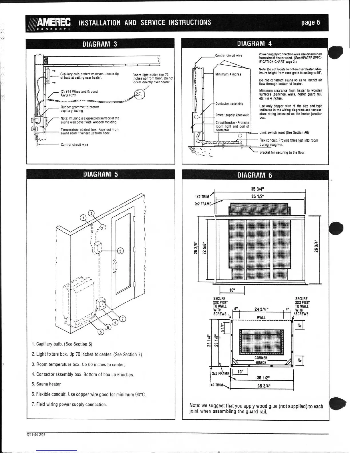
Room light outlet box 70
inches up from floor. Do not
locate directly over heater.
Capillary bulb protective cover. Locate tip
of bulb at ceiling near heater.
(2)114 Wires and Ground
AWG 90"C
Minimum
4 inches
DIAGRAM 4
Power supply connection wire size determined
from size of heater used. (See HEATER SPEC-
IFICATION CHART page 2.)
Note: Do not locate benches over heater. Min-
imum height from rock grate to ceiling is 46'.
Do not construct sauna so as to restrict air
flow through bottom of heater.
Minimum clearance from heater to wooden
surfaces (benches, walls, heater guard rail,
etc.) is 4 inches.
Use only copper wire of the size and type
indicated in the wiring diagrams and temper-
ature rating indicated on the heater junction
box.
Limit switch reset (See Section #6)
Flex
conduit. Provide three feet into room
durin rough-in.
Bracket for securing to the floor.
DIAGRAM 6
Control circuit wire
Contactor assembly
Power supply knockout
Circuit breaker- Protects
room light and
coil of
contactor
DIAGRAM 3
Rubber grommet to protect
capillary tubing
7
—
Note: If tubing is exposed on surface of the
sauna wall cover with wooden molding.
Temperature control box. Face out from
sauna room five feet up from floor.
Control circuit wire
DIAGRAM 5
1.
Capillary bulb. (See Section 5)
2.
Light fixture box. Up 70 inches to center. (See Section 7)
3.
Room temperature box. Up 60 inches to center.
4.
Contactor assembly box. Bottom of box up 6 inches.
5.
Sauna heater
6.
Flexible conduit. Use copper wire good for minimum 90°C.
7.
Field wiring power supply connection.
35 3/4"
1X2 TRIM
/
2x2
35 1/2"
•
to
in
CV
CV
10"
SECURE
2X2 POST
TO WALL
SCREWS
I
4"
WITH
SECURE
2X2 POST
TO WALL
WITH
/SCREWS
24 3/4 "
WALL
CORNER
BRACE
1x2
2x2 FRAMEfn
i-le“
1
35 1/2"
35 3/4"
Note: we suggest that you apply wood glue (not supplied) to each
joint when assembling the guard rail.