speed is held constant as the motor load changes. To calibrate the IR/T:
1. Set the IR/T trim pot full CCW.
2. handheld tachometer may be used to measure motor speed.
2.
2.
5. Unload the motor.
If using tach feedback, calibrate the IR/T trim pot as follows:
2.
2.
2. the armature voltage across A1 and A2 using a voltmeter.
6. Set the IR/T trim pot to full CW.
2. step 3.
to either A90/A180 or TACH.
calibrate FWCL:
1. With the power disconnected from the drive, connect a DC ammeter in series with the motor
2. armature.
5. Apply line power. The motor should be stopped.
2. armature current.
8. Remove line power.
9. Remove the stall from the motor.
10. Remove the ammeter in series with the motor armature if it is no longer needed.
Reverse Current Limit (RVCL):
for minimum speed. To calibrate the OFS1:
1. Set the OFS1 trim pot at 50%.
crossing / zero speed command. To calibrate the OFS1:
1. Set the OFS1 trim pot at 50%.
for minimum speed. To calibrate the OFS2:
1. Set the OFS2 trim pot at 50%.
crossing / zero speed command. To calibrate the OFS2:
1. Set the OFS2 trim pot at 50%.
Maximum Speed (MAX):
Signal 2 inputs. To calibrate the MAX:
1. Set the MAX trim pot full CCW.
1. With the power disconnected from the drive, connect a DC ammeter in series with the motor armature.
point is below the current limit.
8. Remove AC line power. Wait 30 seconds before reapplying power.
Calibration
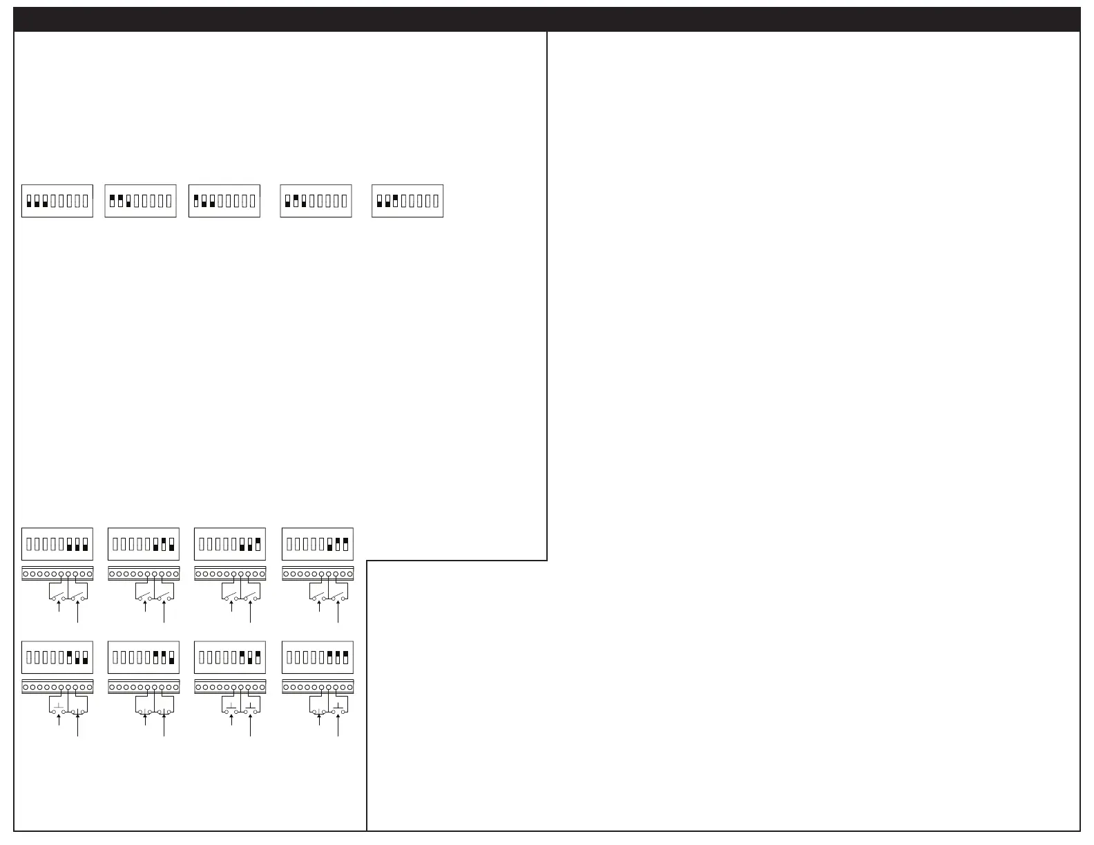
Open to Start
Close to Stop
1 2 3 4 5 6 7 8
Close to Start
Close to Stop
1 2 3 4 5 6 7 8
Open to Start
Open to Stop
1 2 3 4 5 6 7 8
Close to Start
Open to Stop
1 2 3 4 5 6 7 8
Enable
Open to Coast
Inhibit
Open to Brake
1 2 3 4 5 6 7 8
Enable
Close to Coast
Inhibit
Open to Brake
1 2 3 4 5 6 7 8
Enable
Open to Coast
Inhibit
Close to Brake
1 2 3 4 5 6 7 8
Enable
Close to Coast
Inhibit
Close to Brake
1 2 3 4 5 6 7 8
Independent Speed/Torque
Mode
1 2 3 4 5 6 7 8
Linear Speed/Torque
Mode
1 2 3 4 5 6 7 8
Torque Mode
1 2 3 4 5 6 7 8
Mode
1 2 3 4 5 6 7 8
Speed Mode
1 2 3 4 5 6 7 8
Speed Mode:
Torque Mode:
Linear Speed/Torque Mode:
Independent Speed/Torque Mode:
The drive will run to set speed upon power up if receiving a run command and the Enable and Inhibit are set to run.
Upon power up, the drive must see a stop command before the drive will run the motor.
Alarm Output Type
The AUX output alarm will turn on whenever the drive is in current limit.
Enable/Inhibit or 3-Wire Start/Stop
Terminals COM and EN are a momentary Start switch and terminals COM and INH are a momentary Stop switch.
Operation
 Loading...