QSG-0135 r 1
document.
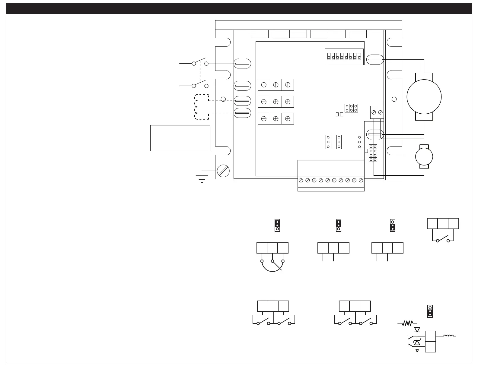
+5V
AUX
COM
5 - 24V
Relay
Coil
OUT IN
AUXILLARY OUTPUT3-WIRE START/STOP*
COM INHEN
CLOSE
TO
RUN
OPEN
TO
STOP
COM INHEN
CLOSE TO RUN
OPEN TO COAST
CLOSE TO RUN
OPEN TO BRAKE
ENABLE / INHIBIT*
*Alternative wiring setups in Operation section
DIRECTION SWITCH
EN COMDIR
Open for Forward
Close for Reverse
4 - 20 mA
SIG1 10VCOM
Common
(-)
Reference
(+)
VDC
mA
SIG1
ANALOG mA
0 - 10 VDC
-10 to 10 VDC
SIG1 10VCOM
Common
(-)
Reference
(+)
VDC
mA
SIG1
ANALOG VDC
10K Ohm
Speed / Torque
Adjust Potentiometer
SIG1 10VCOM
CW
VDC
mA
SIG1
POTENTIOMETER
US
10A
5A
2.5A
1.7A
A2 A1
F- F+
L2L1
COM SIG1 10V SIG2 DIR EN COM INH COM AUX
OUT IN
SIG2SIG1
VDC
mA
T1 T2
A180
A90
TACH
J504
STAT
LIMIT
1 2 3 4 5 6 7 8
ON
IR/TRACCFACC
MOPRVCLFWCL
MAXOFS2OFS1
TACH 0 ± 180 VDC
MOTOR
ARMATURE
0 ± 90 VDC
0 ± 180 VDC
MOTOR FIELD*
100 / 200 VDC
*DO NOT MAKE ANY
CONNECTIONS TO F- OR F+
IF USING A PERMANENT
MAGNET DC MOTOR
EARTH
GROUND
AC LINE INPUT
115 or 230 VAC
POWER
SWITCH
Connect the AC line power leads to terminals L1 and L2, or to a double-throw,
at a minimum of 250 VAC and 200% of motor current.
Connect the DC armature leads to terminals A1 and A2. If the motor does not
Do not make
Enable
The enable is used to start the drive. It can be set for a normally open or normally
The enable can also be used as a Start switch in a 3-Wire Start/Stop setup.
Inhibit
FACC and RACC trim pots. It can be set for a normally open or normally closed
Connections
 Loading...