Installation Instructions
VIEW MANAGER 96 ENHANCED TOUCH TRACKER 8000-0748-02, REV. B1
INSTALLATION INSTRUCTIONS 1 of 6
1View Manager
®
96
Enhanced TOUCH
TRACKER
®
Contents
About This Document ....................................................1
Planning the T
OUCH TRACKER Network...........................1
Backbone Network Guidelines...................................2
Star Network Guidelines ............................................2
Installing Enhanced T
OUCH TRACKERS............................3
Configuring T
OUCH TRACKERS for Use with VM96 ..........4
Connecting T
OUCH TRACKERS .....................................4
Remote T
OUCH TRACKER Overview.................................5
Remote Touch Tracker Installation ............................6
About This Document
This guide explains how to install and configure
the VM96 Enhanced Touch Tracker. Other related
documents are:
• Communications Protocols and Cable
Networks (PN 8000-2573-19)
• View Manager 96 Version 5.0 System
Operator's Manual (PN 8000-2635-01)
• View Manager 96 Version 5.0 Quick
Reference Guide (PN 8000-2636-05)
• View Manager 96 Version 5.0 System
Administrator's Manual (PN 8000-0756-05)
If you need assistance...
Call your sales representative.
View Manager and Touch Tracker are trademarks of
Sensormatic Electronics Corporation. Other product names (if
any) mentioned herein may be trademarks or registered
trademarks of other companies.
No part of this guide may be reproduced in any form without
written permission from Sensormatic Electronics Corporation.
RLJ 05/2005
© 2005 Sensormatic Electronics Corp.
Planning the Touch Tracker
Network
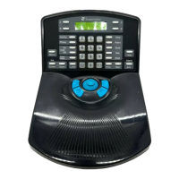
Figure 1: VM96 Equipment
The VM96 system supports a maximum of eight
Touch Tracker controllers (controller). Controllers
can attach in a variety of configurations, but must
follow all SensorNet configuration and termination
rules.
• A network link's maximum length is 1000m
(3300 feet).
• Each network link supports up to 32 devices
and up to four network branches.
• The VM96 console provides four SensorNet
links. SensorNet J-Boxes provide additional
links.
• Each Touch Tracker controller attaches to the
network via an External Interconnect Module
(EIM), which provides the controller with power
and network termination.
The guidelines included in this document provide
brief descriptions about how to implement
Enhanced Touch Trackers in a Backbone or Star
network. For detailed information about the various
network types and communication protocols, refer
to Communications Protocols & Cable
Networks (PN 8000-2573-19).
Power Supply
External Interconnect
Module
Touch Tracke
Console
SensorNet