AMERICAN Flow Control
Series 2500 Resilient Wedge Gate ValvePage 3A-4
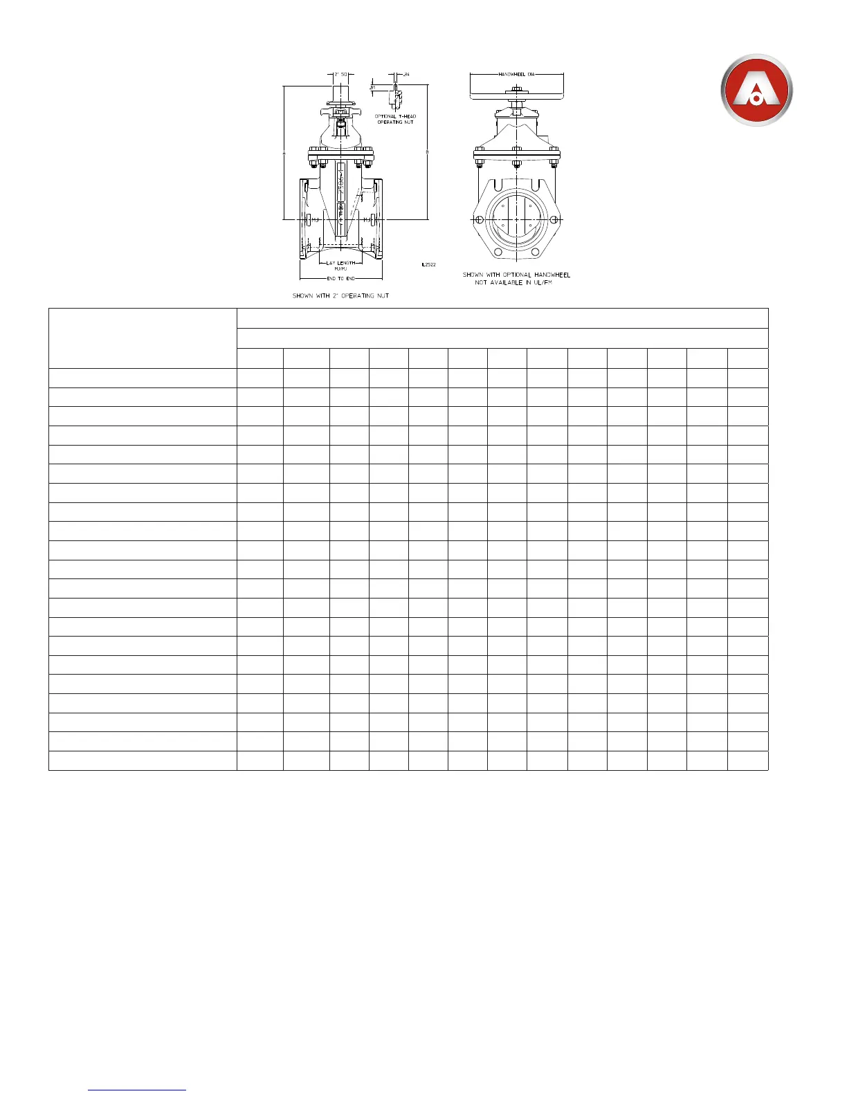
SERIES 2500 - STANDARD NRS DIMENSIONS, 2”–24” SIZES
Dimension Series 2500 / Series 2500-1
2” 2-1/2” 3” 4” 6” 8” 10” 12” 14” 16” 18” 20” 24”
A 8.44 11.03 11.84 13.91 17.12 20.47 24.06 27.59 33.25 36.75 39.62 43.25 51.25
B 9.36 12.00 N/A N/A N/A N/A N/A N/A N/A N/A N/A N/A N/A
C Waterway Diameter 2.06 2.50 3.19 4.25 6.25 8.25 10.25 12.25 14.19 16.19 18.12 20.12 24.12
End to End - MJ/MJ 7.75 N/A 8.62 10.00 10.50 11.50 12.50 13.50 20.50 20.88 23.00 23.50 25.62
Lay Length - MJ/MJ 2.75 N/A 3.62 5.00 5.50 6.50 7.50 8.50 13.50 13.88 16.00 16.50 18.62
End to End - FL/FL (Class 125) 7.00 7.50 8.00 9.00 10.50 11.50 13.00 14.00 15.00 16.00 17.00 18.00 20.00
End to End - FL/FL (Class 250) N/A N/A 11.12 12.00 15.88 16.50 18.00 19.75 18.50 21.00 22.00 24.00 26.38
End to End - TY/TY N/A N/A N/A 13.00 15.88 17.50 18.75 19.75 N/A N/A N/A N/A N/A
End to End - PO/PO (Push-On) N/A N/A N/A N/A N/A N/A N/A N/A 22.16 24.66 N/A N/A N/A
End to End - FL/MJ (Class 125) N/A N/A 8.31 9.50 10.50 12.38 13.62 14.38 17.75 18.44 20.00 20.75 22.81
End to End - FL/TY (Class 125) N/A N/A N/A 11.00 13.19 14.50 15.88 16.88 N/A N/A N/A N/A N/A
End to End - PVC/PVC 10.75 11.12 11.38 13.00 15.88 17.50 N/A N/A N/A N/A N/A N/A N/A
End to End - Threaded 5.0 7.38 7.38 N/A N/A N/A N/A N/A N/A N/A N/A N/A N/A
End to End - FX/FX (Flex-Ring
®
) N/A N/A N/A N/A N/A N/A N/A N/A N/A 28.50 N/A 31.50 34.50
Lay Length - FX/FX (Flex-Ring
®
) N/A N/A N/A N/A N/A N/A N/A N/A N/A 13.62 N/A 15.12 16.62
End to End - AA/AA (ALPHA™)
N/A N/A N/A 11.34 12.81 16.22 17.34 18.96 N/A N/A N/A N/A N/A
Lay Length - AA/AA (ALPHA™)
N/A N/A N/A 4.24 5.32 6.37 7.15 8.31 N/A N/A N/A N/A N/A
End to End - AX/AX (ALPHA™ XL)
N/A N/A N/A 12.64 13.40 17.38 18.30 20.27 N/A N/A N/A N/A N/A
Lay Length - AX/AX (ALPHA™ XL)
N/A N/A N/A 4.24 5.32 6.37 7.15 8.31 N/A N/A N/A N/A N/A
Handwheel Diameter 7.00 8.00 8.00 10.00 12.00 14.00 16.00 16.00 20.00 20.00 20.00 28.00 28.00
No. of Turns to Open 9 11 13 14 20 26 32 38 44 50 56 62 76
3 in.–54 in. valves meet or exceed requirements of ANSI/AWWA C515.
2in.–18in.valvesmaybeorderedincongurationswhichareULListedandApprovedbyFMApprovals.
20in.–24in.valvesmaybeorderedincongurationswhichareULListed.
2 in.–48 in. valves have 250 psig AWWA rated working pressure.
2in.–18in.valvesinListedandApprovedcongurationshave250psigULandFMratedworkingpressure.
20in.–24in.valvesinListedcongurationshave175psigULratedworkingpressure.
Fusion bonded epoxy coating meets or exceeds requirements of ANSI/AWWA C550.
Bolt patterns of Class125angedendsareinaccordancewithANSI/AWWAC110/A21.10(ASMEB16.1Class125).
Threaded ends are in accordance with ASME B16.4, Class 125.
Mechanical joint ends are in accordance with ANSI/AWWA C111/A21.11.
Push-on ends are in accordance with ANSI/AWWA C111/A21.11 for use on ductile iron pipe sizes. Valves are furnished with TYTON
®
(TY) ends.
TYTON
®
isaregisteredtrademarkofUnitedStatesPipeandFoundryCo.,LLC.
PVC ends are suitable for use on steel (IPS) sizes of PVC or steel pipe.
2in.–66in.valvesareCertiedtoNSF/ANSIStandard61andNSF/ANSI372.
Valves for use with raw sewage should be orientated with valve stems vertical.
ALPHA™isatrademarkofRomacIndustries,Inc.(U.S.Patent8,894,100)
NOTES:
1.
2.
3.
4.
5.
6.
7.
8.
9.
10.
11.
12.
13.
14.
 Loading...