AMERICAN Flow Control
Series 2500 Resilient Wedge Gate Valve
Page 3A-6
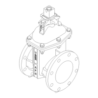
SERIES 2500 - NRS WITH BEVEL GEARING DIMENSIONS, 14”–66” SIZES
Dimension
Valve Size
Series 2500
14” 16” 18” 20” 24” 30” 36” 42” 48” 54” 60” 66”
A 35.19 39.75 43.00 44.44 52.62 62.62 74.38 86.28 96.00 96.00 118.00 118.00
B 9.50 9.50 9.50 10.38 10.38 13.56 15.38 19.19 19.19 19.19 19.19 19.19
C Waterway Diameter 14.19 16.19 18.12 20.12 24.12 30.22 36.19 42.38 48.38 48.38 60.50 60.50
End to End - MJ/MJ 20.50 20.88 23.00 23.50 25.62 33.75 37.50 46.75 45.00 N/A N/A N/A
Lay Length - MJ/MJ 13.50 13.88 16.00 16.50 18.62 25.75 29.50 38.75 37.00 N/A N/A N/A
End to End - FL/FL (Class 125) 15.00 16.00 17.00 18.00 20.00 26.00 30.00 38.00 43.00 48.00 53.00 58.00
End to End - FL/FL (Class 250) 18.50 21.00 22.00 24.00 26.38 32.00 37.00 40.00 46.25 N/A N/A N/A
End to End - PO/PO (Push-On) 22.16 24.66 N/A N/A N/A N/A N/A N/A N/A N/A N/A N/A
End to End - FL/MJ (Class 125) 17.75 18.44 20.00 20.75 22.81 29.88 22.75 42.38 44.00 N/A N/A N/A
End to End - FX/FX (Flex-Ring
®
) N/A 28.50 N/A 31.50 34.50 41.00 44.50 53.50 62.00 N/A 71.00 N/A
Lay Length - FX/FX (Flex-Ring
®
) N/A 13.62 N/A 15.12 16.62 21.75 25.19 31.75 37.25 N/A 44.88 N/A
Handwheel Diameter 12.00 12.00 12.00 20.00 20.00 20.00 20.00 32.00 32.00 32.00 36.00 36.00
No. of Turns to Open 88 100 112 186 228 379 448 694 798 798 984 984
 Loading...