Do you have a question about the American Standard ACONT602AF22MA and is the answer not in the manual?
Details system types, settings, and fan options for the comfort control.
Covers power options and selectable manual or auto-changeover modes.
Emphasizes trained technician installation, electrical hazards, and mercury disposal.
Provides instructions for proper disposal of old controls containing mercury.
Install approximately 5 feet above the floor in an area with good air circulation.
Avoid drafts, direct sunlight, appliance heat, concealed pipes, and unheated areas.
Lists items included in the product package: thermostat, guide, anchors, and batteries.
Lists necessary tools like screwdrivers, drill, hammer, pencil, electrical tape, and level.
Instructions on how to detach the wallplate from the new comfort control.
Steps to attach the wallplate to the wall, including drilling and securing.
Steps for connecting wires to the terminal block and securing the wall opening.
Explains the meaning of conventional and heat pump terminal letters.
Specifies wire gauge and notes that shielded cable is not required.
Wiring diagram for a single-stage gas furnace with a single-stage air conditioner.
Wiring diagram for a single-stage oil furnace with a single-stage air conditioner.
Wiring diagram for a two-stage gas furnace with a single-stage air conditioner.
Wiring diagram for a two-stage variable speed gas furnace with two-stage cooling.
Wiring diagram for a heat pump with air handler and electric heater.
Wiring diagram for a two-stage 16 SEER cooling system with a two-stage gas furnace.
Details requirements for powering the Comfort Control using 24 VAC power.
Explains how backup batteries save settings during power interruptions.
Instructions on how to attach the Comfort Control to the installed wallplate.
Configures the thermostat for different system types like gas, oil, heat pump, and conventional.
Sets fan control for heating mode based on furnace type (gas/oil vs. electric).
Sets the heating cycle rate in cycles per hour for various furnace and boiler types.
Configures the cycle rate for second stage heating or auxiliary heat.
Allows adjustment between manual and auto changeover modes.
Sets a delay for compressor restarts to prevent damage.
Selects temperature display units between Fahrenheit and Celsius.
Chooses between 5/2 (weekday/weekend) and 5/1/1 (day/day/day) schedule formats.
Guides users through testing heating, cooling, and fan systems.
Tests the heating system, including first and second stage heat.
Tests the cooling system, including compressor and fan operation.
Warns about bypassing compressor protection during testing, advising caution.
Notes that heat and cool settings must be at least 3 degrees apart for Auto Changeover.
Describes how the thermostat displays 'Cool On' or 'Heat On' flashing during the delay.
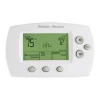
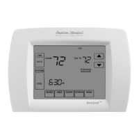
Identifies key control elements like the digital display, function buttons, and hold button.
Shows current temperature, time, system status, settings, and warnings.
Troubleshooting steps for a blank display, checking power and door closure.
Troubleshooting for unresponsive temperature settings, checking ranges and stops.
Troubleshooting steps for heating system issues, checking voltage and wiring.
Troubleshooting steps for cooling system issues, checking voltage and wiring.
Troubleshooting for system setting changes and display status problems.
Details operating temperature ranges, ambient conditions, and electrical ratings.
| heating temperature range | 40° to 90°F (4.5° to 32°C) |
|---|---|
| cooling temperature range | 60° to 99°F (15.5° to 37°C) |
| operating ambient temperature | 32° to 120°F (0° to 48.9°C) |
|---|---|
| shipping temperature | -20° to 120°F (-28.9° to 48.9°C) |
| operating relative humidity | 5% to 90% (non-condensing) |
| terminal voltage | 20-30 Vac |
|---|---|
| W (O) heating running current | 0.02-1.0 A |
| W1 W2 heating running current | 0.02-0.5 A |
| Y cooling running current | 0.02-1.0 A |
| Y2 cooling running current | 0.02-1.0 A |
| G fan running current | 0.02-0.5 A |
| X2 emergency heat running current | 0.02-1.0 A |
| F heat pump reset running current | 0.02-0.5 A |
| height | 3-9/16” (91 mm) |
|---|---|
| width | 5-13/16” (147 mm) |
| depth | 1-1/2” (38 mm) |