Do you have a question about the American Standard IFD AIR CLEANER and is the answer not in the manual?
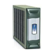
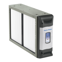
Identifies pre-filter, field charger, collector cells, cabinet, power door, and transformer.
Explains how the air cleaner uses ionization and charged cells to capture particles.
Explains the layered plastic strip design and electrical properties of cells.
Warns against UV light causing plastic deterioration of the filter.
Shows the wiring connections for furnace or air handler systems.
Illustrates transformer connections and test procedures for voltage checks.
Explains the air cleaner's LED display functions and status indicators.
Instructions on turning the unit on and its initial status indicators.
Guide to entering set-up for timer and power adjustments.
Information on ozone production, power levels, and their settings.
Explains fault indicators, their meaning, and how to access logged faults.
Lists recommended actions for each detected fault code.
Tests the high voltage relay function and output.
Verifies the functionality of the unit's various LEDs.
Checks the high voltage output levels for proper operation.
Verifies correct signal reception from the thermostat.
Details expected voltage readings for different output tests.
Confirms correct operation of thermostat signals like heating or blower call.
Uses a probe to measure high voltage output from the power door.
Uses common tools to check for arcing in the power door.
Methods for cleaning the pre-filter by vacuuming or washing.
Recommendations for cleaning collection cells, including washing instructions.
Detailed steps for safely cleaning the field charger pins.
Checks for power door installation, cabling, and 24V AC supply.
Indicates a dry cycle or lack of call for operation, checks HV supply.
Points to foreign material in cells/charger, needs cleaning.
Indicates service is needed, refers to fault code information.
| Brand | American Standard |
|---|---|
| Model | IFD AIR CLEANER |
| Category | Air Cleaner |
| Language | English |