EasyManua.ls Logo

AMERITRON ATR-20 - User Manual

AMERITRON ATR-20
10 pages
Print Icon
To Next Page IconTo Next Page
Loading...
ATR-20 Instruction Manual Ameritron Antenna Tuner
1
1.0 INTRODUCTION
The ATR-20 is a high power antenna tuner. The ATR-20’s roller inductor "T" matching network
continuously tunes all frequencies from 1.8 through 30 MHz. It also features a built-in 3 kilowatt peak or
average detecting directional power meter. The ATR-20 has rear panel connectors for coaxial and wire
feedlines. A heavy duty, high voltage insulated, current-type balun allows use with balanced feedlines.
Properly tuned, the ATR-20 safely operates on all bands with RF power levels of 1.2 kilowatts SSB and
600 watts CW with load impedances from 25-800 ohms. Matching range also extends from one ohm to
2500 ohms (5 ohms to 500 ohms on 160 meters) at slightly reduced power ratings. Peak and average
forward power, reflected power, and SWR are displayed on an illuminated cross-needle meter.
An internal six position antenna-selector switch selects three coaxial line outputs, or a single wire line-
balanced line output. Two coaxial line outputs, ANTENNA 1 and 2, are available in either “tuned”
(with tuner's matching network in line) or “direct” (no matching circuit) configurations.
Coaxial output port ANTENNA 3 is available only as a direct (no matching system) configuration.
WIRE / BALANCED LINE positions are available only as “tuned” configurations.
1.1 Understanding Power Ratings
Unlike amateur radio service amplifiers (commonly rated in RF power output delivered to 50 ohm
resistive loads), tuners have no standard power rating method. Power level descriptions (i.e. “3 kW
Tuner”) used for tuners often carry over from the time when amplifiers were rated by peak power input.
For example, the Kilowatt Johnson Matchbox was designed to handle a typical 1000 watt dc input plate
modulated AM transmitter. Such transmitters developed 3000 watts PEP RF output on AM. Matching
tuners were called one kilowatt tuners.
Years later SSB became popular. The Heathkit SB-220 was called a two kilowatt amplifier, even though
rated CW output was approximately 600 watts. Tuners from the same era were called 2 kilowatt tuners,
because they safely handled the 2 kilowatt PEP input SB-220. The 2 kW tuner only had to handle 600
watts of CW and 1200 watts PEP SSB to be compatible with a 2 kW amplifier of the same era.
Around 1980, the FCC changed the amateur radio power rating system from dc power amplifier input
power to RF envelope (output) power. Most tuners stayed with the old system, and no longer follow
amplifier power ratings. Typical “1500 watt tuners” safely handle only 400-600 watts CW, and 600-900
watts PEP SSB.
Note: This tuner is rated by true RF output power, not by the old method of using amplifier peak input
power.
Load conditions and control settings greatly affect tuner power ratings. T-networks typically handle
more power on higher frequency bands into higher load impedances. The worst operating condition (for
T network tuners) is a low-impedance capacitive-reactance load. T-network tuners handle the least
power on 160 meters with low-impedance capacitive-reactive loads.
Follow the guidelines in this manual to avoid exceeding the ratings of this tuner!
Question and Answer IconNeed help?

Do you have a question about the AMERITRON ATR-20 and is the answer not in the manual?

Summary

ATR-20 Introduction

ATR-20 Power Rating Explanation

Explains ATR-20 power rating methods, comparing old vs. new standards and factors affecting tuner ratings.

ATR-20 Peak Reading SWR;Wattmeter

Details how to use the cross-needle meter for forward/reflected power and SWR measurement.

ATR-20 Antenna Selector

Describes the function of the antenna selector switch and its connector options.

ATR-20 Installation

ATR-20 Power Source Connection

Instructions for connecting a 12 Vdc or 9V battery power source for the meter.

ATR-20 Antenna Connection Procedures

Guide to connecting coaxial, single wire, and balanced line antennas to the tuner's ports.

ATR-20 Grounding Requirements

Details the importance and method of connecting the tuner to the station ground buss.

ATR-20 Operation

ATR-20 Initial Antenna Tuning

Step-by-step guide for tuning the antenna using the ATR-20 for optimal SWR.

ATR-20 Operating Hints

ATR-20 Troubleshooting Common Issues

Guidance for when the tuner fails to tune or experiences internal arcing.

ATR-20 Grounding

ATR-20 Antenna System Hints

ATR-20 Location Considerations

Recommendations for antenna placement for optimal performance.

ATR-20 Matching Problems and Solutions

Explains common impedance matching issues and provides suggestions to resolve them.

ATR-20 Technical Assistance

Overview

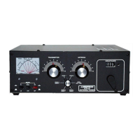
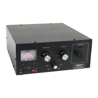
The Ameritron ATR-20 is a high-power antenna tuner designed for amateur radio use, capable of continuously tuning frequencies from 1.8 through 30 MHz. It features a roller inductor "T" matching network and a built-in 3 kilowatt peak or average detecting directional power meter. The tuner includes rear panel connectors for both coaxial and wire feedlines, and a heavy-duty, high-voltage insulated, current-type balun for use with balanced feedlines.

Function Description:

The primary function of the ATR-20 is to match the impedance of a transmitter to various antenna systems, ensuring efficient power transfer and minimizing reflected power (SWR). The continuous tuning capability across the 1.8-30 MHz range makes it versatile for different amateur radio bands. The integrated directional power meter allows users to monitor forward power, reflected power, and SWR, which are crucial for proper antenna tuning and safe operation.

The tuner's antenna selector switch offers six positions: three coaxial line outputs and one single wire/balanced line output. Two coaxial outputs (ANTENNA 1 and 2) can be used in either "tuned" (with the matching network engaged) or "direct" (bypassing the matching circuit) configurations. The third coaxial output (ANTENNA 3) is exclusively for "direct" operation. The WIRE / BALANCED LINE positions are always in "tuned" configurations.

Important Technical Specifications:

  • Frequency Range: 1.8 through 30 MHz (continuous tuning).
  • Power Rating:
    • 1.2 kilowatts SSB (safely operates with load impedances from 25-800 ohms).
    • 600 watts CW (safely operates with load impedances from 25-800 ohms).
    • Matching range extends from 1 ohm to 2500 ohms (5 ohms to 500 ohms on 160 meters) at slightly reduced power ratings.
    • The tuner is rated by true RF output power, not by the older method of amplifier peak input power.
  • Power Meter: 3 kilowatt peak or average detecting directional power meter.
    • Full scale forward power ranges: 300 watts (LO) and 3000 watts (HI).
    • Full scale reflected power ranges: 60 watts (LO) and 600 watts (HI).
    • SWR is read directly from eleven red SWR curves (1:1 to infinity).
  • Balun: Heavy duty, high voltage insulated, current-type balun for balanced feedlines.
  • Power Source for Meter: External 12 Vdc supply (negative ground only) or internal 9 Volt battery. The meter lamp requires an external 12 Vdc supply.
  • Meter Backlighting: Meter and turns counter are backlit with internal lamps, powered by an external 12 Vdc source.

Usage Features:

  • Cross-Needle Meter: Displays peak or average FORWARD power, peak or average REFLECTED power, and SWR simultaneously.
  • METER Switch: Controls full scale forward and reflected power range (300W LO / 3000W HI).
  • PEAK/AVG Push Button: Selects between Peak Envelope Power (PEP) and average power readings.
  • Antenna Selector Switch: Allows selection between three coaxial outputs (tuned or direct) and a wire/balanced line output (tuned only).
  • Tuning Controls: ANTENNA, TRANSMITTER (capacitors), and INDUCTANCE (roller inductor) controls for impedance matching.
  • Tuning Procedure:
    1. Tune exciter into a dummy load.
    2. Select desired antenna.
    3. Set initial ANTENNA, TRANSMITTER, and INDUCTANCE controls based on a provided table for each band.
    4. Apply low power (25-50 watts) with the POWER switch in LO and AVG positions.
    5. Adjust INDUCTANCE (counter-clockwise from recommended position) for lowest reflected power/best SWR.
    6. Adjust ANTENNA and TRANSMITTER controls for lowest reflected power. Repeat until SWR is as close to zero as possible.
    7. If SWR doesn't reach 1:1, adjust INDUCTOR counter-clockwise (to a lower number) and repeat step 5.
    8. For maximum power handling and efficiency, always adjust capacitors to the lowest front panel number (highest capacitance) and use the lowest possible inductance (highest number on the turns counter) that allows proper antenna matching.
    9. Fully advance power and fine-tune controls for minimum reflected power.
    10. Record control settings for quick retuning.
  • Battery Saver: An RF controlled solid state battery switch electronically disconnects the internal battery after a short period of inactivity to extend battery life.
  • Meter ON/OFF Switch: Controls meter and turns counter lamps, and turns off meter circuitry when using battery power.

Maintenance Features:

  • Grounding: Requires a good DC and RF ground connection to minimize RFI and ensure safety. A wing nut post marked GROUND is provided for this purpose. It is crucial to connect the tuner to a good outside earth ground or water pipe ground, and ensure this safety ground also connects to the transmitter and other station accessories.
  • Safety Warnings:
    • Never operate with the top removed due to high RF voltages.
    • Never rotate the ANTENNA SELECTOR switch while transmitting to prevent damage.
    • Locate the tuner to prevent contact with rear panel ceramic feed-throughs when using balanced or single wire feedlines, as these can carry high RF voltages.
    • Disconnect all antennas during lightning storms.
    • Tune with low power (less than 100 watts) before applying high power.
  • Troubleshooting: If the tuner fails to tune or arcs at rated power levels, double-check connections, re-follow tuning procedures, and ensure proper inductance and capacitance settings. If internal arcing persists, reducing transmitter output power or modifying antenna/feedline length may be necessary.
  • Antenna System Hints: Provides guidance on balun usage (1:1 current type balun for ladder line, choke-type balun at feedpoint for balanced antennas), avoiding unbalanced antennas with balanced feedlines, and optimizing antenna/feedline balance to reduce RFI. It also offers advice on antenna location and specific feedline lengths to avoid common matching problems, especially for multi-band antennas.

The ATR-20 is designed for robust performance, but proper installation, grounding, and adherence to tuning guidelines are essential to maximize its efficiency and prevent damage.

AMERITRON ATR-20 Specifications

General IconGeneral
BrandAMERITRON
ModelATR-20
CategoryTuner
LanguageEnglish

Related product manuals