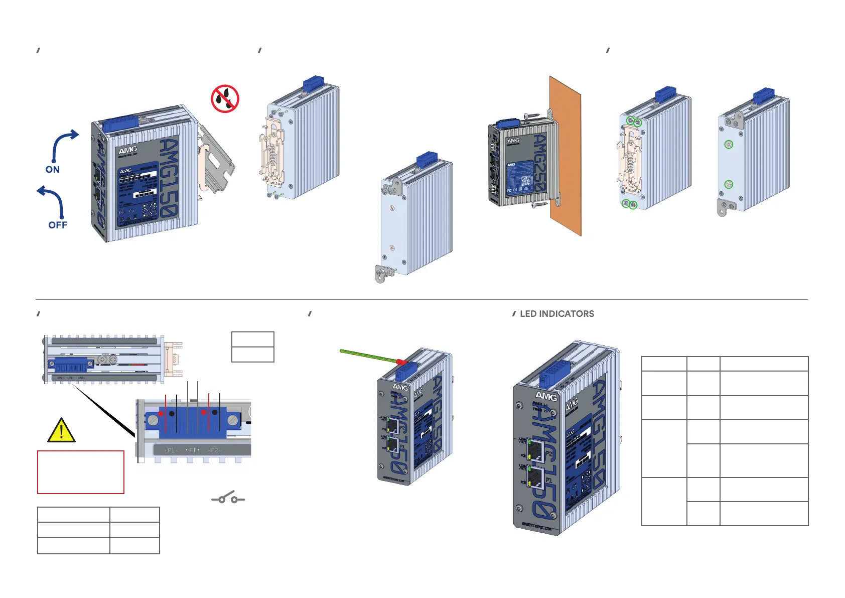
DIN RAIL MOUNT INSTALLATION
POWER
SURFACE MOUNT INSTALLATION
③ Fix the unit to the surface
using two appropriate screws
(screws not provided)
LED INDICATORS
① Remove the DIN rail clip
by unscrewing the two xing
screws as shown.
② Attach the included wall
mount brackets with the
provided 4 x M3 screws as
shown.
IP RATING
To maintain the units IP40 rating any
screw holes that are not used should still
have their screws installed as shown in
green above.
Warning
Do not exceed the rated
voltage Observe correct
voltage polarity
Fault relay is normally closed
and will open on either power
failure. If used with a single
PSU, the PSU should be
wired to both power inputs.
Model Type Voltage
30W PoE Models 48-56 VDC
90W PoE Models 52-56 VDC
Power
2W Max*
*Excludes PoE Load
+
-
Power 1
Power 2
Fault Relay
60V @ 2A Max
LED Colour Description
POWER 1 Blue
DC input present on
power 1
POWER 2 Blue
DC input present on
power 2
RJ45
LINK/ACT
O
No Ethernet link
connection
Green
Ethernet link present
(ashes with data
trac activity)
POE
O
No PoE being
supplied
Yellow
PoE is being delivered
on the port
EARTH PROTECTION
To provide correct protection from ESD
and Surge events ensure that the unit
is correctly earthed using the provided
earth connection point in accordance
with local electrical codes & standards.
(cable not provided)
+
-
 Loading...