15www.ampmaker.com
In each case, insert the screw from the outside and don't forget the shakeproof washers (remember that
ampliers are subjected to a lot of vibration). Make sure to choose the correct size washer for the screw
- don't use the M3 washers with M2.5 hardware, or you'll run out when you need them!
Then add the hole cover to the unused hole between V1 and V2 and insert the ve rubber grommets.
There are two sizes, but it's not possible to get them mixed up. Now attach the four M6 cagenuts to the
outside (top) of the chassis anges.
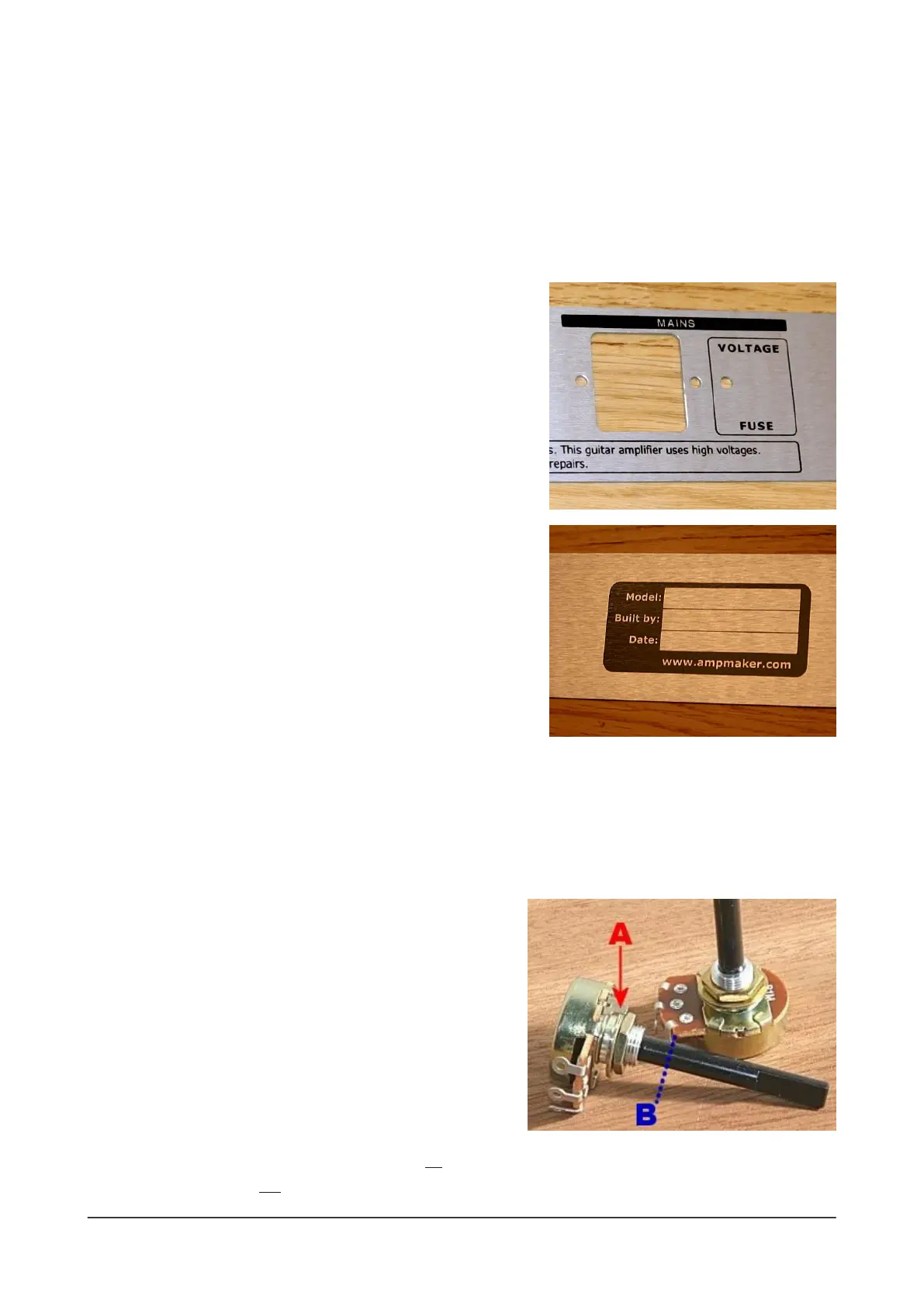
Rear panel and components
Just four sockets and four sets of hardware to do here. But it's
easier to add your country's mains voltage and the fuse
information before you mount the rear panel. Use a permanent
marker pen to write in these two pieces of information in the
box provided at the right end of the panel. Your mains voltage
will be one of 100/120/220/230/240V and the fuse value will be
"T500mA".
There's also a pre-printed box for you to personalise your
amplier build in the centre of the panel. Write in your own
details here.
Now add the rear panel and secure it in place with M4
hardware with ground lug at the far right end of the chassis
(when viewed from the inside), and M4 hardware (without a
ground lug) at the far left.
Then add the three speaker output sockets, orientating
them so that the solder lugs are all facing out of the chassis for
soldering later. Add the IEC mains socket and secure it with M3
hardware (using the countersunk screws).
Front panel and controls
The N5X's front panel is held in place by the main amplier controls: six pots, three switches, one lamp
and one socket. However, for now, install only the six pots to allow easy access for other parts later.
(Keep J1, S1, S2, S3 and L1 on one side.) When installing the pots, there are a few things to bear in mind:
1) trim the black nylon shaft (B) so that it's about 8mm long - use a junior hacksaw, Dremel with cutting
wheel or similar
2) use BOTH plain washers on the inside of the chassis...
3) ...to allow the small locating tab (A) to t in the small holes
in the front of the chassis (bend it slightly, if necessary)
One minor thing to bear in mind: the order of the pots
along N5X panel isn't sequential! The pots are numbered
according to the schematic - as they should be - but it's
obviously conventional to put the Middle pot (VR4) between
the Treble pot (VR2) and the Bass pot (VR3) on the front
panel. :)
TIP: Double-check that you have the single 1M lin pot in the VR6 position for the Power control for the
VCB circuit. The two 1M log pots are for Bass (VR3) and Master (VR5).
 Loading...