20 N5X Construction guide
Wiring the neon indicator
Prepare the neon indicator for soldering by gently prising the two solder
tags away from the black plastic - use a thin-bladed screwdriver. This
makes it easier to add a wire to each tag's solder hole.
Find the thin brown wire in the wire pack - the type that has just a
single solid strand (instead of the thicker multi-stranded type). Solder two
wires to the neon indicator, one to each lug and then twist them gently
together and run them across to the centre lugs of the On/O switch. Connect one to each lug and now
you can solder all four wires in place.
Adding the MOSFET
Next, you add the MOSFET. But before we even touch that, here are
some vital safety points:
1) MOSFET devices can be damaged by static, including small charges
that build up on your body. If you're susceptible to static shocks, then
pay special attention - places with low humidity (air conditioning in use)
can be tricky. Here's a site with a useful guide on static: http://
www.wikihow.com/Remove-Static-Electricity - each time before I pick
up a MOSFET, I touch something that I know is grounded (a radiator, another amplier chassis that's
plugged into the mains, etc) to discharge any static.
2) The #1 tip here is: keep handling to a minimum. Pick it up only when you need it, and do the whole
process as a single operation.
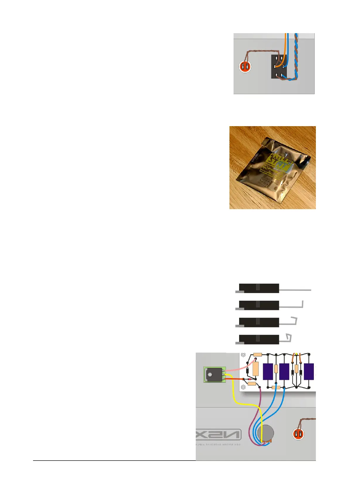
3) This MOSFET carries a high voltage on its metal mounting tab so you MUST properly insulate it from
the chassis. There's a sticky SILPAD supplied with the kit for this
reason.
MOSFETs such as these are modern devices, designed for insertion in
PCBs. For hand-wired layouts, it's a good idea to tweak their
connection pins to make them easier to connect. Start by creating a
solder lug for each of the three legs of the MOSFET. Use needle-nose
pliers to carefully bend the legs upwards and round to make a ring or
hook that you can more easily solder to.
Now add the sticky SILPAD to the underside of the
MOSFET, making sure that the holes line up and the whole
of the MOSFET's underside is covered. Then mount it to the
chassis using M3 hardware (using the 10mm M3 screw).
There are two holes here; use the one that allows the
MOSFET to clear the power supply board and orientate the
MOSFET so that the 'lugs' are closest to the board. Do not
overtighten the nut.
Finally, add the three connecting wires between the
MOSFET and the board and Power level pot.
 Loading...