19www.ampmaker.com
Mains-side wiring
With the turret board properly installed, you can add the On/O switch (S3) and the neon indicator (L1)
to the front panel. (For clarity, the front and back panels are shown here as if they have been folded
down, although in reality they are at the usual 90 degrees to the bottom of the chassis.)
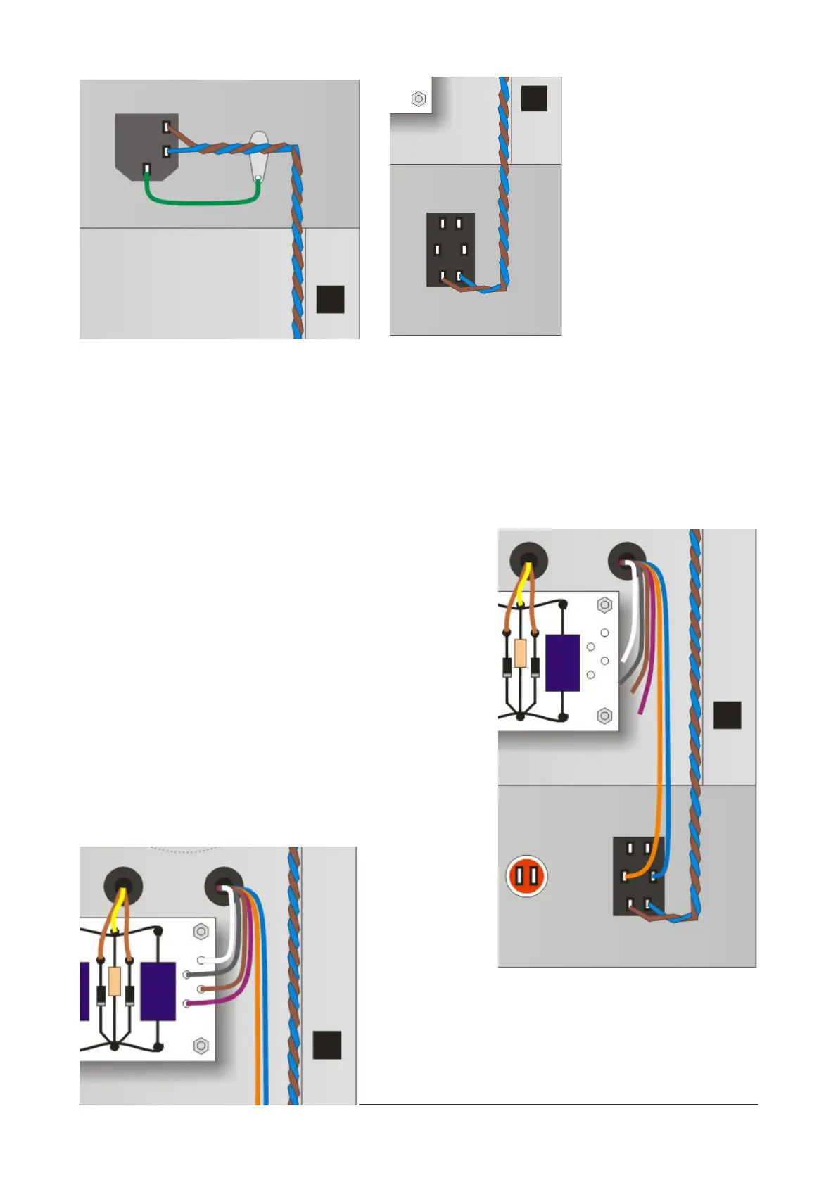
The rst job is to add three wires to the IEC socket: a short green wire to connect the Earth lug
directly to the grounding lug next to the IEC socket, and a brown and blue wire to the Live and Neutral
lugs. Run the brown and blue wires along the side of the chassis to the On/O switch, twisting them
together and solder them to the top pair of lugs on the On/O switch.
Then connect the six remaining wires from the power
transformer. First, choose the correct two wires for your mains
supply:
* 100V = white and blue
* 120V = grey and blue
* 220V = brown and blue
* 230V = purple and blue
* 240V = orange and blue
Run these two wires over to the On/O switch and trim and
connect them, one to each of the switch's centre lugs. Don't
solder them just yet, however. (The diagram to the right shows
the orange and blue wires in use for a 240V connection for UK,
Australia, etc.)
You now have
four wires left over,
the colours will
depend on those you
chose for your mains
supply of course.
Run these four wires to the four turrets on the right of the
board. Trim them to length and solder them now. (If you move
to another country with a dierent mains supply, you can
alter this wiring in the future.)
 Loading...