18 N5X Construction guide
Initial power supply wiring
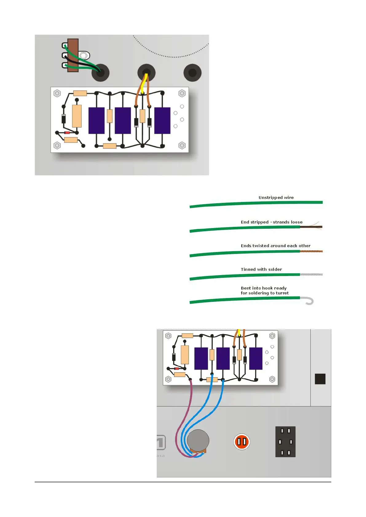
There are three sets of wires from the power
transformer. The rst two sets connect as follows:
1) Green + black + green wires to the 3-way
tagstrip close to the rst rubber grommet. Trim
each wire and solder it to the relevant solder tag.
2) Brown + yellow + brown wires to the turret
board as shown here.
For each of these wires, it’s best to tin the end
with solder and then bend it to create a ‘hook’ that
you can place around each turret shaft - shown
above in step-by-step form). Use needle-nose
pliers to crimp the hook around the shaft of the
turret and then solder it into place.
Then connect the VCB circuit's Power
control (VR6) to the turret board with three
wires as shown here. Solder lugs 2 and 3,
but leave lug 1 unsoldered for the moment.
As usual with hand-wired amplier layouts
- in general it's best to keep wires as short
as possible and routed directly. Avoid
unnecessarily long wires.
 Loading...