17www.ampmaker.com
Building the power supply
In the N5X, we build and test the power supply (including the smaller turret board and the VCB circuit)
before building the rest of the amplier. Start by gathering up the turret board and the following
components:
* R20
* R22
* R23
* R24
* R25
* R26
* C13
* C16
* C17
* D1
* D2
* D3
* D4
* the bare bus wire
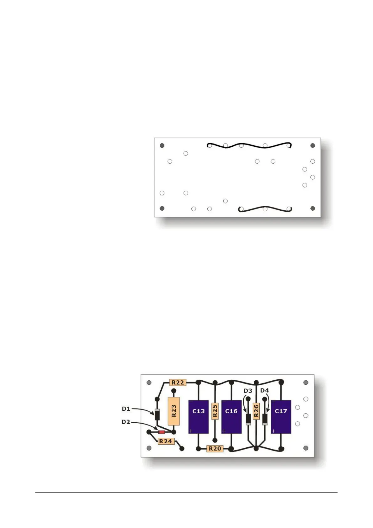
The rst job is to add two lengths of bare bus wire to the top and bottom row of turrets, as shown above.
Solder each wire to the side of the turret that it passes, eight solder joints in all.
TIP: Amp builders have their own technique but if you're not sure, you can weave the wire around the
turrets (as shown above), and at each end wrap the wire around the last turret.
Add power supply components
Now trim and solder the components to the board, as shown in the diagram below. A few notes to help
you:
1) For diodes D3 and D4, it’s best to solder them to the sides of the turrets. This leaves the turret hole
available for you to add the high voltage supply wires.
2) Pay attention to the orientation of the following components: C13, C16, C17, D1, D2, D3 and D4. Make
sure they are connected as shown in this diagram. (If you've ever made an Amp Maker kit, pay special
attention, because this
set of three capacitors
are the opposite way
around to kits such as
the WF-55, SE-5a, PP-18,
etc!)
Now mount this
turret board in the
chassis. Use an M3
shakeproof washer and
M3 nut for each of the
four mounting points.
 Loading...