26 N5X Construction guide
Adding the board components
Take your time as you populate the turret board with components. Double check that you have the right
component before you trim its leads ("measure twice and cut once").
Some components are a tight t and it's worth doing a 'dry
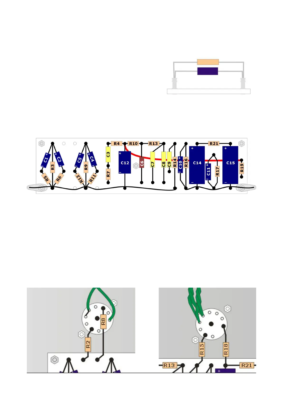
run' before you start soldering. In particular C14 and C15 are
quite bulky and make it a little tricky to solder adjacent
components. One way around this is to solder C10+R16 and
C11+R17 one above the other, as shown in this diagram.
Note that all of the blue/black capacitors have a polarity and
in this turret board the negative terminal of all of them points towards ground. (Note that for reasons
that are lost in the mists of time, it's conventional to indicate positive terminals on schematics, but
negative terminals on the capacitors themselves. So I've shown both on this diagram to make things
clear!)
TIP: If you nd it dicult to get several component leads into one turret top, you can also solder the
leads to the side of the turret instead. As long as you have a good solder joint, it's electrically (and
tonally) identical.
Final turret board components
With the on-board components added, you have a handful of components left over: R1, R2, R8, R15 and
R18. Most of these connect the turret board to the valve sockets.
Now trim and solder R2 and R8 in place, connecting the board to the V1 valve socket (pins 2 and 7,
respectively). See below.
For resistors R15 and R18, trim them to length and solder them at the turret board end only. (You will
add an extra wire and solder them to the V2 valve socket later.)
 Loading...