27www.ampmaker.com
Turret board wiring
The next step is to add wires to connect the turret board with the valve sockets and front panel controls.
In each case, keep it as neat and direct as possible. When soldering to valve socket pins, make sure that
you avoid wire 'whiskers' where one strand of wire misses its hole and shorts against a neighbouring pin
or the chassis.
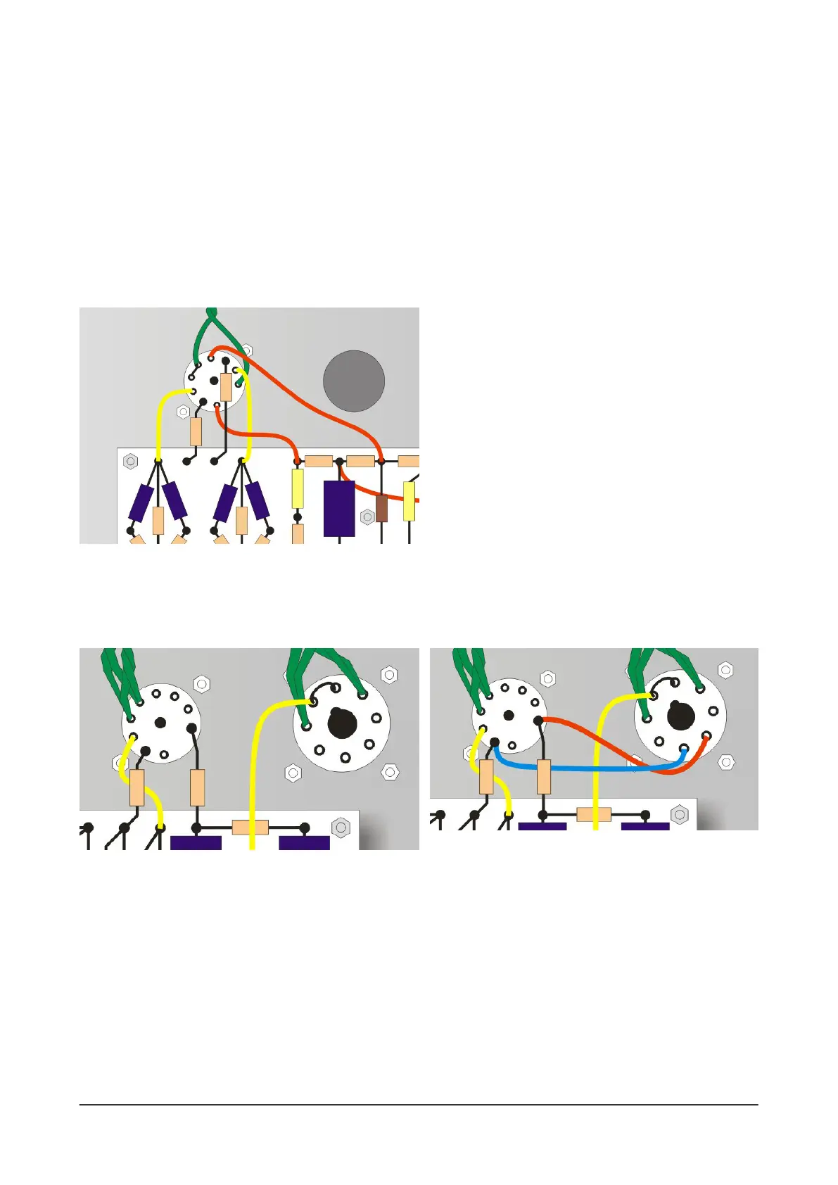
Start with the V1 connections. Two red wires connect to the anodes of V1, pins 1 and 6, and two
yellow wires to connect to their cathodes, pins 3 and 8. That completes the V1 wiring and it should look
like this:
Then make the two yellow wire connections for V2 and V3. This connects their cathodes to the
turret board. Pay special attention to V3 - you must strip a little extra wire so that you can extend the
connection from pin 1 to 8, soldering the wire at both pins.
Now there are two wires that connect V2 directly to V3. These also complete the R15 and R18
connections (which were left unsoldered from the previous page):
* add a blue wire to connect R15 at pin 2 of V2 to pin 5 of V3
* add a red wire to connect R18 at pin 9 of V2 to pin 4 of V3
Solder all four pins and V2 and V3 should now look like this:
Note that there are several unused pins on V2 and V3 - we'll return to some of these a little later.
 Loading...