R E S E A R C H
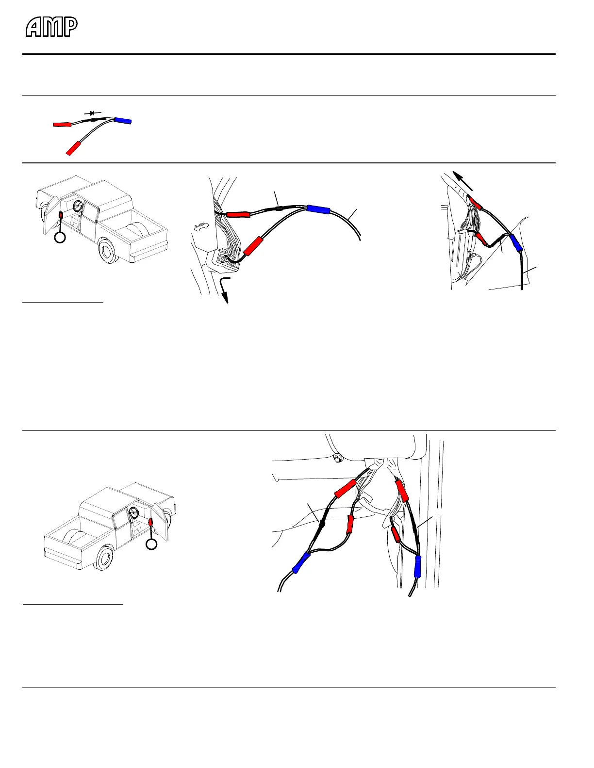
PASSENGER SIDE WIRING
1. After removing the front door step plate and kick plate, lift carpet
and pull Powerstep trigger wires through floor of truck.
2. Locate the rear door-ajar signal wire (dark blue with white stripe)
on black connector below the hood-release lever (Area-A in Figure A
-1). There should be two wires of this color; use the wire located on
the row closest to the plug release.
3. Cut this wire and install Single Diode Harness as oriented in
Figure A-2.
4. After timming to correct length, connect the light blue with black
stripe trigger wire from step one to the blue connector of Single
Diode Harness installed in previous step.
5. Locate the front door-ajar signal wire (tan) on large connector
located behind the connector of step 2.
6. Cut this wire and install Single Diode Harness as oriented in
Figure A-3.
7. After timming to correct length, connect the grey with black
stripe trigger wire from step one to the blue connector of Single
Diode Harness installed in previous step.
8. Wrap all connections with electrical tape and secure any loose
wires.
Notes:
1. All of the signal wires tapped into will be 18Ga. Do not tap into anything with a thicker gage than this.
2. Occassionally the wire colors do not match the wire schematics. Under these circumstances you will need to locate the door-ajar signal wires.
3. Make sure to secure all wires after install. Loose wires can be damaged and may cause a failure in the Powerstep's function.
Diode
Diode
1. After removing the front door step plate, lift carpet and pull
Powerstep trigger wires through floor of truck.
2. Locate the two wire bundles running up along kick panel area
underneith glove compartment as shown in the above figures.
3. Open wire wrap of the bundles and locate the front and rear door-
ajar signal wires (dark blue with white stripe), one found in each
bundle.
B
Figure B-1
4. Cut each wire and install the Single Diode Harnesses as
oriented in Figure B-2. Make certain that the leg with the
diode is towards the top.
5. Wrap all connections with electrical tape and secure any
loose wires.
Figure B-2
Revision - 06/15/10
(Call 800-315-9705 to receive diodes free of charge.)
A
Figure A-1
Single Diode Harness Kit - Qty: 4 pcs.
ATTENTION: Pay close attention to the
orientation of the diode harnesses. The
Power-Step will not work with a incorrectly
installed diode harness.
Part # 10-02727-90





 To Next Page