SVT 210AV Speaker Cabinet
3
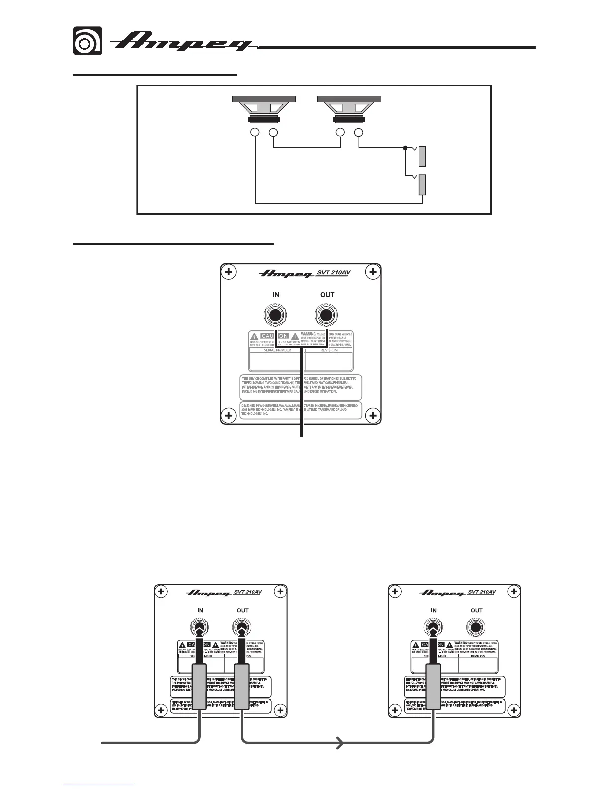
System Block Diagram
1. 1/4" TS Input and Output Jacks: Connect the speaker-level output of your amplifier
(rated up to 200W into 8 ohms) to the input jack using good quality (non-shielded) speak-
er cable. Never use (shielded) instrument cable to connect speakers to an amplifier.
You can use the output jack to connect a second speaker cabinet in parallel. This will
present a total load of 4 ohms to the amplifier (maximum power input = 400 watts rms
into 4 ohms).
Rear Panel Connector Plate



 To Next Page