Parts Identification
Front View
1. 1/4” STEREO PHONE JACK
2. LCD DISPLAY
2 X 18 character LCD displaying units parameters and programming instructions.
4. CONTROL BUTTONS
Buttons for Menu, various playback, recording and volume controls
5. FRONT MESSAGE ACTIVATION SHORT KEY
PAGE 2 MR1301 MESSAGE RECORDER / PLAYER
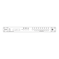
Rear View
1
3 4
11
14
DC 24V
+
2
5
6
7
8 9
10
12 13
3. RECORD LED
In recording mode, the red LED shall flash.
6. POWER CONNECTORS
24V DC input for power, use only regulated power supply or Amperes PS9400 power supply unit.
7. POWER SWITCH
Power switch for the unit.
8. RESET BUTTON
Button for resetting the unit to factory default. Use only when required as settings done previously would be lost. Voice
files stored in the SD card shall not be affected.
Stereo phone jack for microphone inputs with balanced input signal. Used for recording voice to the unit. It accepts record-
ing via dynamic microphone.
8 front short key for direct message activation ; MES 1 to MES 16 with LED indicators. Shift button is available for trigger-
ing message 9 to 16.