EasyManua.ls Logo

Amprobe AMB-25 User Manual

Amprobe AMB-25
8 pages
To Next Page IconTo Next Page
Page #1 background imageLoading...
Page #1 background image
INSULATION TESTER
1. SAFETY INFORMATION
The circuit under test must be de-energized and isolated before
connections are made except for voltage measurement.
Verify operation prior to measuring hazardous voltages (voltage
above 30V AC rms, 42V AC peak and 60V DC).
AMB-25
Do not touch the Circuit connections during a test.
Disconnect the live test lead before disconnecting the neutral
test lead.
INSTRUCTION MANUAL
After insulation tests, to protect electric shock, capacitive circuits
must to be discharged.
READ
MEM
Caution refer to this manual before using the meter.
Dangerous voltages.
Meter is protected throughout by double insulation or
reinforced insulation.
Comply with IEC1010-1
When servicing, use only specified replacement parts.
s
AC
m:
HOLD
VG
K
M
Do not use the meter if the low battery indicator (
BT
) is
showed.
Test leads (including crocodile clips) must be in good order,
clean and no broken or cracked.
Do not use the meter if it looks damaged.
Do not use the meter around explosive gas, vapor or dust.
Do not push test button before all connection and preparation is
done. The instrument must only be used by suitably trained and
competent persons.
Do not use the meter with any parts or cover removed.
Do not use the meter in a wet environment.
U.S. PAT. NO. 478,017
JAPAN PAT. NO. 1180870
CHINA PAT. NO. ZL02367250.1
Warnings and Safety symbols:
1
www. .com
information@itm.com1.800.561.8187
Question and Answer IconNeed help?

Do you have a question about the Amprobe AMB-25 and is the answer not in the manual?

Amprobe AMB-25 Specifications

General IconGeneral
TypeDigital Multimeter
ContinuityYes
Diode TestYes
AC Voltage Range600V
DC Voltage Range600V
DisplayDigital LCD
Measurement RangeVaries by function
ResolutionVaries by range
Operating Temperature0 °C to +40 °C

Summary

1. SAFETY INFORMATION

Circuit Isolation and Voltage Verification

Ensure circuit is de-energized and verify operation before measuring hazardous voltages.

2. SPECIFICATIONS

Electrical Specifications

Insulation resistance ranges, resolution, accuracy, test voltages, resistance & continuity.

3. PARTS & CONTROLS

Component Identification

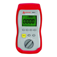
Identifies LCD display, MEM, LOCK, READ, Zero, TEST keys, rotary switch, and input terminals.

Key Functions Explained

Details functions of MEM, LOCK, READ, Zero, and TEST keys for data management and testing.

4. BEFORE OPERATION

5. Ω RESISTANCE AND CONTINUITY MEASUREMENTS

Resistance and Continuity Measurement

Steps to measure resistance and continuity, including voltage check and beeper indication.

6. MΩ INSULATION RESISTANCE MEASUREMENTS

Measuring Insulation Resistance

Steps for measuring insulation resistance, emphasizing safety precautions and test voltage application.

8. FUSE CHECK & REPLACEMENT

9. BATTERY REPLACEMENT

Related product manuals