Do you have a question about the Amprobe AT-6020 and is the answer not in the manual?
General safety and handling instructions for safe operation.
Specific safety measures to avoid electrical shock and injury.
Explains various symbols used in the manual and on the instrument.
Details product compliance with safety standards and directives.
Important warnings and precautions to understand before operating the instrument.
Guidelines for proper terminal use, lead connection, and battery handling.
Outlines procedures for warranty and non-warranty repairs and replacements.
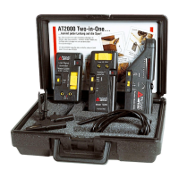
Lists the main components included in the AT-6020 and AT-6030 kits.
Details the contents of the test lead and accessory kit and optional accessories.
Detailed illustration and labeling of the AT-6000-R Receiver's parts.
Detailed illustration and labeling of the AT-6000-T Transmitter's parts.
Explains the High, Low, and Loop modes of the AT-6000-T Transmitter.
Details usage of High, Low, and Loop modes under different circuit conditions.
Explains the Receiver's active and passive tracing methods.
Illustration and labeling of the CT-400 Signal Clamp accessory.
Explains signal cancellation and the need for separate ground connections.
Step-by-step guide for connecting test leads to the Transmitter.
Instructions for powering on and selecting HIGH signal mode.
Guide for using the Receiver in Quick Scan mode for initial wire detection.
Guide for precise wire pinpointing using Precision Tracing mode.
How the Receiver identifies breakers/fuses and connection methods.
Steps to set up the Transmitter for breaker locating.
Instructions for using the Receiver to scan and identify breakers.
Advice for improving breaker identification accuracy.
How to use NCV mode to detect energized wires and verify status.
Performing passive tracing and adjusting sensitivity.
Methods for tracing wires in GFCI protected circuits.
How to locate breaks or opens in wires using Precision Tracing.
Procedure for finding shorted wires using Loop mode.
Guidelines for tracing wires inside metal conduits.
Method for tracing conduits or pipes using fish tape.
Procedures for effectively tracing shielded wires.
How to trace wires located underground.
Tracing data, audio, and thermostat cables.
Method to identify a single wire within a bundle.
Performing circuit mapping using test leads on de-energized circuits.
Precautions for tracing breakers on systems with light dimmers.
Using the signal clamp for tracing closed loop circuits.
How to connect the CT-400 Signal Clamp to the Transmitter.
Setting up the Transmitter in Loop mode with the signal clamp.
Using the Receiver with the signal clamp for tracing.
Using the signal clamp to map loads to specific breakers.
Proper positioning of the Receiver's tip sensor for mapping.
Step-by-step guide for replacing the batteries in the Transmitter, including access and installation.
Manual and automatic methods for setting the Transmitter's battery type.
How to interpret the battery level indicators for both battery types.
Instructions for replacing the batteries in the AT-6000-R Receiver.
Step-by-step guide for replacing the fuse in the Transmitter.
Detailed technical specifications for the AT-6000-R Receiver and AT-6000-T Transmitter.
Covers display, operating environment, certifications, and dimensions.