EasyManua.ls Logo

Amprobe AT-6010 User Manual

Amprobe AT-6010
30 pages
To Next Page IconTo Next Page
Page #1 background imageLoading...
Page #1 background image
AT-6010
Advanced Wire Tracer
User Manual
ENG FRE
SPA
w ww . . co m
information@itm.com1.800.561.8187

Other manuals for Amprobe AT-6010

Question and Answer IconNeed help?

Do you have a question about the Amprobe AT-6010 and is the answer not in the manual?

Amprobe AT-6010 Specifications

General IconGeneral
BrandAmprobe
ModelAT-6010
CategoryGPS
LanguageEnglish

Summary

Warranty and Repair Information

Limited Warranty Details

Details warranty coverage, limitations, and disclaimers for Amprobe products.

Product Service and Repair

Procedures for returning Amprobe products for warranty or non-warranty repair.

Precautions and Safety Measures

General and Specific Safety Guidelines

General instructions for safe operation, handling, and specific warnings.

Symbols and Compliance Information

Explanation of safety symbols and product compliance with standards.

Safety Information and Warnings

Product Compliance and Directives

Details product compliance with safety standards and directives.

Critical Usage Warnings

Critical warnings and precautions to prevent injury or damage.

Additional Safety and Product Information

Battery Safety and Shipping Contents

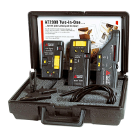
Safety advice for battery handling and list of shipping box contents.

AT-6010-R Receiver Overview

Receiver Controls and Features

Overview of the AT-6010-R Receiver, its controls, and display.

AT-6010-T Transmitter Overview

Transmitter Signal Modes

Explains the High Signal (Hi) and Loop modes for the Transmitter.

Transmitter Operation and Safety

Connecting and Operating the Transmitter

Instructions on connecting and operating the Transmitter, including voltage warnings.

Transmitter Indicators and Modes

Transmitter Controls and LEDs

Overview of the Transmitter's buttons, LEDs, and battery status indicators.

Energized vs. De-energized Modes

Explains the difference between Energized (6 kHz) and De-energized (33 kHz) modes.

CT-400 Signal Clamp Accessory

Signal Clamp Description and Use

Description of the optional CT-400 Signal Clamp accessory and its applications.

Main Applications - Signal Cancellation

Avoiding Signal Cancellation Issues

Explains how to avoid signal cancellation problems with a separate ground connection.

Main Applications - Wire Tracing Setup

Connecting Test Leads and Transmitter

Instructions for connecting test leads to the Transmitter for tracing.

Setting Up the Transmitter for Tracing

Steps for turning on and configuring the Transmitter for tracing.

Using the Receiver for Wire Tracing

Tracing Mode Operation

How to use the Receiver in tracing mode to find signal strength and wire location.

Receiver Positioning for Accuracy

Tips for aligning the Receiver's Tip Sensor for optimal signal detection.

Applications - Identifying Breakers and Fuses

Breaker/Fuse Identification Methods

Methods for identifying breakers and fuses using the Transmitter and Receiver.

Test Lead Connection Methods

Explains simplified and separate ground connection methods for test leads.

Applications - Locating Breakers

Transmitter Setup for Breaker Location

Steps for setting up the Transmitter for breaker identification tasks.

Receiver Scanning for Breakers

How to use the Receiver to scan breakers and identify the correct one.

Special Applications - GFCI and Wire Breaks

Tracing GFCI Protected Circuits

Methods for tracing wires in GFCI protected circuits without tripping protection.

Finding Breaks or Opens in Wires

Procedure for pinpointing the location of broken or open wires.

Special Applications - Shorts and Conduit Tracing

Finding Shorts in Wires

Procedure for tracing and locating shorted wires.

Tracing Wires in Metal Conduit

Method for tracing wires within metal conduits where signal is shielded.

Special Applications - Non-Metallic Conduits and Shielded Wires

Tracing in Non-Metallic Conduits

Tracing wires inside non-metallic conduits and pipes using fish tape.

Tracing Shielded Wires

Procedures for effectively tracing shielded wires.

Special Applications - Underground and Low Voltage Cables

Tracing Underground Wires

Tracing underground wires using the same methods as wall/floor tracing.

Tracing Low Voltage and Data Cables

Tracing low voltage, data, audio, and thermostat cables.

Special Applications - Bundled Wires and Circuit Mapping

Sorting Bundled Wires

Procedure for identifying a specific wire within a bundle.

Mapping a Circuit with Test Leads

Method for mapping a circuit using test leads connection on a de-energized circuit.

Special Applications - Light Dimmers and Signal Clamp

Tracing Breakers with Light Dimmers

Precautions when tracing breakers on systems with light dimmers.

Signal Clamp for Closed Loop Circuits

Using the signal clamp to trace closed loop, de-energized circuits.

Special Applications - Signal Clamp for Mapping Loads

Mapping Loads to Breakers with Clamp

Using the signal clamp to map loads to specific breakers on circuits.

Maintenance - Transmitter Battery Replacement

Replacing Transmitter Batteries

Step-by-step guide for replacing batteries in the Transmitter.

Maintenance - Receiver Battery Replacement

Replacing Receiver Batteries

Step-by-step guide for replacing batteries in the Receiver.

Maintenance - Transmitter Fuse Replacement

Replacing Transmitter Fuse

Procedure for replacing the fuse in the Transmitter.

Specifications - Core Product Specs

Receiver, Transmitter, and Clamp Specs

Technical specifications for the Receiver, Transmitter, and Signal Clamp.

General Specifications Overview

Receiver and Transmitter General Specs

Detailed general specifications for the AT-6010-R Receiver and AT-6010-T Transmitter.

Accessory Specifications

TL-6000-INTL Test Lead Specs

Technical specifications for the TL-6000-INTL test lead and accessory kit.

Related product manuals