8
2.1.2 REAR PANEL
24. Ventilation ports - Exhausts warm air from the unit.
25. GPIB Interface - 24 pin parallel GPIB interface connector.
26. Voltage Selector - Selects voltage of either 115VAC or 230(240)VAC, -10% ∼ +10%, 50/60Hz.
27. Fuseholder - Fuseholder for AC line.
28. AC receptacle - AC plug for power cord.
29. Negative Terminal (-) - Negative rear screw terminal output for hard wiring.
30. Positive Terminal (+) - Positive rear screw terminal output for hard wiring.
31. -S - Negative rear screw terminal for remote sense output. Enables hard wiring.
32. +S - Positive rear screw terminal for remote sense output. Enables hard wiring.
33. Ground Terminal - ground rear screw terminal.
34. External analog input voltage for programming output voltage. Input voltage ranges from 0 Volts to 10 Volts.
35. Voltage external programming reference point.
36. External analog input voltage for programming output current. Input voltage ranges from 0 Volts to 10 Volts.
37. Current external programming reference point.
<NOTES:>
1. The rear panel configuration is identical on all power supplies. However, the PPS-2322 has an
additional terminal strip for hard wiring the second channel.
2. The PPS-1603 and the PPS-10710 have an external programming input terminal located at the
rear of the supply. Please refer to section 3.7 for further information.
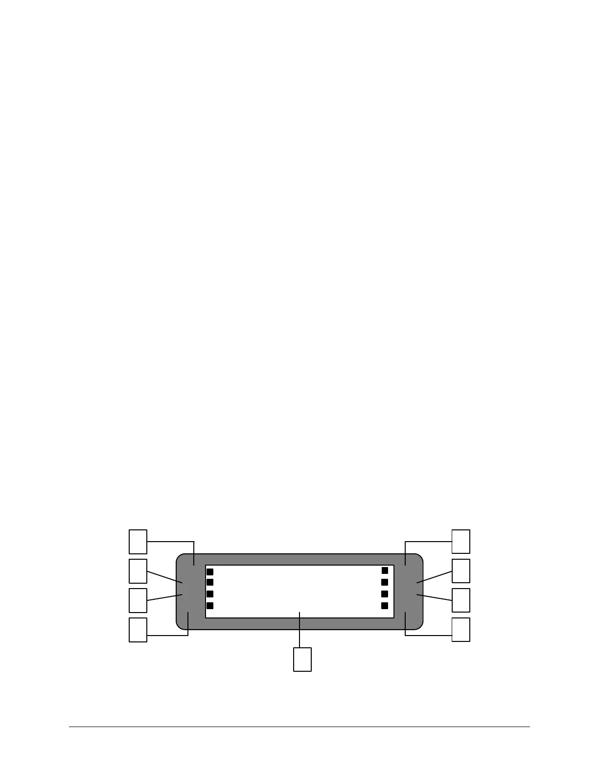
2.2 LCD STATUS ANNUNCIATORS
LIQUID CRYSTAL DISPLAY: Figure F-1, F-2, F-3
OCP1
CC2
30.00V * 0.000A
1 5
CC1
TRK
RMT OVP1
OVP2
OCP2
I NPUT ERROR!
2
3
4
6
7
8
9
Figure F -1. LCD of PPS-2322
www.valuetronics.com
 Loading...