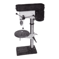
MODEL 4030
5 SPEED DRILL PRESS
INSTRUCTION MANUAL
ASSEMBLY : OPERATING
MAINTAINANCE : PARTS LIST
ATTENTION: READ CAREFULLY BEFORE ATTEMPTING TO
INSTALL, OPERATE OR SERVICE YOUR AMT DRILL PRESS.
PROTECT YOURSELF AND OTHERS BY OBSERVING ALL SAFETY
INFORMATION AND ADDITIONAL INSTRUCTIONS INCLUDED WITH
THIS EQUIPMENT. FAILURE TO COMPLY WITH INSTRUCTIONS
COULD RESULT IN PERSONAL INJURY AND/OR PROPERTY
DAMAGE! RETAIN FOR FUTURE REFERENCE.
ASSEMBLY
1. Open the box and remove the base, working table
assembly, and column assembly. Place the base
on a flat surface and fasten the column assembly
to the base using four cap screws, key #4, and
four split washers, Key #3.
shaft. See "Changing Speeds" section for speed
selection and belt tension.
WARNING: Wiring of
the motor and switch should be accomplished
by a qualified electrician.
TABLE ADJUSTMENTS
A. Height Adjustment: To adjust work table, Key
#10, up or down, hold the table with one hand
and loosen the clamp bolt, Key #9, then raise
or lower the table to the desired position and
retighten the clamp bolt.
2. Slip the working table assembly onto the column
and slide it down until it rests on the base.
B. Tilting Work Table: To tilt the work table to the
right or left, loosen bolt, Key #13, and tilt
the table to the desired angle up to 45° and
retighten bolt, Key No. 13.
3. Remove the head stock assembly and position it
on top of the column and secure it in place by
tightening two socket set screws key #15.
4. Assemble knobs, Key #26, onto one end of pull
down handles, Key No. 25, and screw the
handle assemblies into the pull down hub, Key
#23.
C. Rotation of Work Table: To rotate the work table,
Key #10, loosen the clamp bolt, Key #9, and
rotate the table to the desired position. The
table is capable of a full 360° rotation. To
obtain more distance between the chuck, Key
#42, and the work table, the work table can be
rotated 180° and the base, Key #1, can be used
as a work table. This will permit the drilling
of larger objects.
5. Install motor using 4 sets of fasteners: (4)
hex cap screws, (8) large washers (4)
lockwashers on nut side, and (4) hex nuts.
These parts are included but not shown on
parts drawing. Install motor pulley key #65
and lock set screw Key #11 on motor