Specications Information and Repair Parts Manual IPT 2P5X, 2S5X, 2S5XC, 3S5X Series
2S5X-250-00 1 2/2018
Please read and save this Repair Parts Manual. Read this manual and the General Operating Instructions carefully before attempting to assemble, install, operate
or maintain the product described. Protect yourself and others by observing all safety information. The Safety Instructions are contained in the General Operating
Instructions. Failure to comply with the safety instructions accompanying this product could result in personal injury and/or property damage! Retain instructions
for future reference. AMT reserves the right to discontinue any model or change specications at any time without incurring any obligation.
©2018 AMT Pump Company, A Subsidiary of The Gorman-Rupp Company, All Rights Reserved.
Periodic maintenance and inspection is required on all pumps to ensure proper operation. Unit must be clear of debris and sediment. Inspect for leaks and loose bolts. Failure to do so
voids warranty.
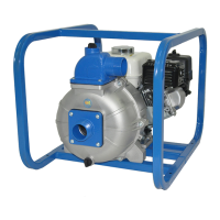
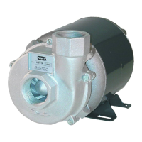
IPT Series 2P5X, 2S5X, 2S5XC & 3S5X Pumps
Refer to pump manual 1808-633-00 for General Operating and Safety Instructions.
SPECIFICATIONS
Standard units are constructed of cast aluminum with cast iron impeller (“P”
series - cast aluminum), cast iron volute, and cast iron suction and discharge
manifolds. Standard seals are EPDM with silicon-carbide (“P” series – carbon-
ceramic) wear faces.
UNPACKING
1. Remove pump from packaging materials.
2. Package should include: pump/engine mounted in roll frame, strainer,
general/safety manual, specication/parts manual, engine manual. Pump
kits: Pump end, general safety manual, and specication/parts manual.
3. Make sure all components are accounted for before discarding packaging
material.
4. Inspect all components for damage.
5. No assembly is required for standard engine driven pumps. Pump kits
must be constructed on appropriate engine.
PREPARING UNIT FOR OPERATION
Placing Pump
1. Always place the pump as close to the liquid source as possible. Priming
eciency and pump output will be reduced if a long (>25 ft.) suction line
is used. Keep all lines as short and straight as possible. Avoid any sharp
bends. Suction line cannot have loops or high spots, hose must have a
gradual slope up to pump.
2. Pump/engine must be located on a solid level surface.
Connecting Hose or Piping
1. All suction hose/piping connection must be air tight. Pump will not prime if
there are any air leaks in the suction line or connections.
2. Use only non-collapsible hose or pipe on the suction. If collapsible hose
is used on the discharge, the end of discharge line is submerged in liquid,
or a check valve is placed in the discharge line, a means of venting air out
of the pump during the priming cycle must be employed.
3. Always use a suction strainer to keep large debris out of the pump. Position
strainer well below liquid surface and on a bed of rocks or other suitable
surface. If possible tie strainer up so it is suspended o pit bottom. As a
last resort tie the strainer in a large submerged bucket if bottom of water
source is too soft or muddy.
Before Starting Engine
1. Fill engine crankcase with oil. Follow engine manufacturer
recommendations for service classication and viscosity of oil as detailed
in engine manual.
2. Fill fuel tank with clean, fresh, fuel. Follow engine manufacturer’s
guidelines as listed in engine manual.
3. Always ll pump with liquid through the priming port located on top of the
discharge manifold or pump casing before starting engine. Remember the
pump is self-priming only when the pump is lled with liquid.
Operation
1. Make certain pump is lled with liquid before starting engine. Failure to do
so will result in damage to the mechanical shaft seal. Never run pump dry.
DO NOT USE PUMP IN EXPLOSIVE ATMOSPHERE. DO NOT PUMP
VOLATILE OR FLAMMABLE LIQUIDS.
2. Follow engine manufacturer’s starting procedure. Run engine at full speed
during priming. After pump has primed speed may be reduced to regulate
pump output.
3. Pump will self-prime to a vertical height of 10’ in less than one minute,
20’ in 2 minutes, 25’ may take up to 4 minutes. If pump doesn’t prime:
Check for air leaks, move pump closer to liquid, shorten suction line,
remove loops and high spots from suction line, rell pump with liquid, see
troubleshooting guide in this manual.
4. Always allow engine to cool before refueling.
After Pump is Shut Down
1. Always ush the pump out at the end of operation if the liquid being
pumped may leave a solid or sticky residue inside of pump, or if a buildup
of sediment inside the pump is expected.
2. Always drain pump completely of liquid if there is a chance of freezing.
DESCRIPTION
IPT engine driven pumps are commercial duty, centrifugal, self-priming (to 25 ft. vertical lift after initially lling casing with liquid), portable units. Pumps are
equipped with industry standard mechanical shaft seals. Iron suction and discharge manifolds are standard male NPT threads for direct connection to swivel
hose tting with gasket, or standard NPT pipe ttings. Discharge manifold can be rotated 180˚ (in 90˚ increments); left side discharge, front discharge or right side
discharge. Pump components will handle liquids with a temperature range of 40˚ to 180˚F (4˚ to 82˚ C). Pump only nonammable liquids compatible with pump
component materials. Standard pumps are close coupled to internal combustion engines manufactured by Honda, Briggs & Stratton, & Hatz, AMT specication
engines and others. All engines meet current EPA emissions requirements. Pumps (70cc and larger) are preempted from emissions regulation in California. Bear-
ing housing/pedestal drive pumps are also available for direct or drive belt connection.