AMX Corporation reserves the right to alter specifications without notice at any time.
For full warranty information, refer to the AMX Instruction Manual(s) associated with your Product(s).
041-004-2648 10/02 ©2002
AMX Corporation. All rights reserved. The AMX logo is a trademark of AMX Corporation. AMX reserves the right to alter specifications without notice at any time.
3000 RESEARCH DRIVE, RICHARDSON, TX 75082 • 800.222.0193 • 469.624.7153 • fax 469.624.7153 • technical support 800.932.6993 • www.amx.com
93-5975
REV: A
Using the MONITOR OUT HD-15 Connector
Connect the VGA display equipment’s HD-15 (male) connector to the MONITOR
OUT HD-15 (female) high-density connector on the rear panel of the panel. The
following table lists the MONITOR OUT connector pinouts.
WARNING! Do not connect the wire from the PWR terminal on the Central
Controller to the PWR terminal on the TPI/3 AXlink connector, since the
TPI/3 uses an external power supply.
Make sure to connect only the AXM, AXP, and GND wires on the TPI/3’s
AXlink connector when using the PSN6.5 power supply.
Configuration
To configure the touch panel, follow these sections in sequence. Use the NetLinx
Studio program to select a COM port and set its parameters, and use the NetLinx
Studio Terminal Emulator to enter the Send Commands described in the following
sections. Alternatively, you can use AXCESS/X or any other terminal program to
communicate with the TPI. Verify that your PC is connected to the PROGRAM port
on the front panel of the TPI.
1. Setting up Communication
1. In NetLinx Studio, select Tools > Master Comm Settings to open the Commu-
nication Settings dialog, where you can select an available COM port.
2. Click the Configure button to set the communication parameters for the
selected COM port.
The default settings for the TPI are: 38,400, 8-bits, No parity, Stop Bits = 1,
and Flow Control = None.
3. In NetLinx Studio, select Tools > Terminal to launch the Terminal Emulator
window.
4. Type
HELLO (you will not see the characters) and press Enter. When a valid
connection exists, the device responds with
HOW ARE YOU DOING.
5. Type ECHO ON and press Enter (now the characters should be displayed on the
screen).
2. Setting the Output Resolution
The output resolution for the monitor must be configured and then calibrated. Refer
to the specifications table for available output resolutions and refresh rates.
1. Verify the connection of the output display monitor to the
MONITOR OUT port
on the rear panel of the TPI.
2. Use the following command in Terminal Emulator mode:
Resolution <hor>x<vert>:<refresh>
example:
Resolution 1024x768:60
Sets the TPI/3 to send a video signal at 1024 x 768 with a refresh rate of 60 Hz.
Note: If the video is blurry, try a different refresh rate and/or resolution. Check the
output device to verify you are using refresh rates and resolution settings are
compatible with the device.
3. Assigning the Touch Drivers
Use the following command and device IDs to set the mouse driver:
Mouse<# for touch driver>
This command allows you to see the characters on the display as you type them. The
following table lists the supported touch devices and their associated ID’s.
example:
Mouse 12
The example sets the touch device to the VTM-D15/A MultiMedia Touch Panel
or
ELO IntelliTouch
®
panel.
• If the assigned
ELO driver does not allow calibration of the monitor, try the alter-
nate
ELO touch driver and repeat step 2.
• Do not calibrate the TPI/3 if you are using a Microsoft
®
compatible mouse or a
mobile mouse.
• Do not enter the <> characters when entering the values or commands, they
are included in the syntax example to visually indicate a field.
4. Calibrating the Monitor
Once the monitor is resized, calibrate it to use the touch drivers. In terminal emulator
mode, there are 4 commands used for calibration:
•
Calibrate sets the monitor to begin the calibration test mode.
•
Get Cal displays the current calibration values.
•
Check Cal allows you to manually check the calibration on the monitor by
using your touch on the panel to display an on-screen cross-hair.
•
Set Cal allows you to manually configure the calibration values for the monitor
if you know the correct calibration values (ex: cloning the TPI). This command
is only supported through a serial connection.
1. Calibrate the TPI by entering:
calibrate
2. Press the on-panel cross-hairs as they appear. After the last cross-hair has
been depressed and the coordinates points have been set, a dialog displays
the panel coordinate values.
3. Press the screen to exit from the calibration session and return to the panel
display.
4. To verify these values, check the calibration of the TPI by entering:
check cal
5. Touch the panel at any location and a cross-hair should appear directly below
the touch point.
5. Verifying Your Settings
1. Ty pe ?PAR into the Terminal software to verify the driver. The touch name
should correspond to the desired driver. The return from the TPI/3 includes
these characteristics:
2. In NetLinx Studio, exit the Terminal Emulator (or exit the AxcessX, HyperTermi-
nal or other telnet program).
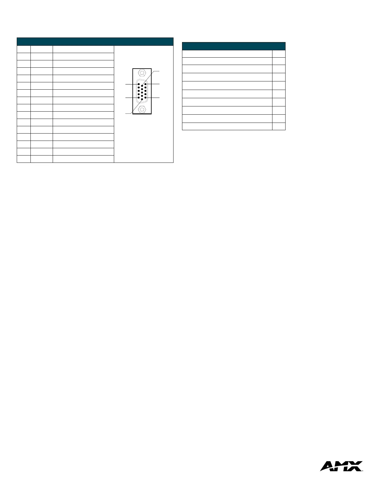
VGA IN HD-15 Connector Pinouts
Pin Signal Function
1 Red Red signals
2 Green Green signals
3 Blue Blue signals
4 N/A Not used
5 GND Signal Ground
6 RAGND Red analog ground
7 GAGND Green analog ground
8 BAGND Blue analog ground
9 N/A Not used
10 SAGND Synchronization analog ground
11 N/A Not used
12 N/A Not used
13 HSYNC Horizontal synchronization signal
14 VSYNC Vertical synchronization signal
15 N/A Not used
VGA HD-15 (male)
10
6
5
1
15
11
Supported Touch Devices / ID’s
Touch Device ID
No touch device 00
Microsoft
®
serial mouse (default)
01
2nd Microsoft Serial Mouse (MX-MM Mobile Mouse
®
)
02
Dynapro
®
touch monitor
10
MicroTouch
®
touch monitor
11
Elo IntelliTouch
®
and VTM-D15/A touch monitors
12
Elo AccuTouch
®
touch monitor
13
EZ Screen
®
touch monitor
15
External touch driver FF
• Version indicates the TPI firmware
version on the TPI.
• Mouse Type displays the mouse driver
assigned for use through the TPI.
• Device # identifies the beginning device
address for the attached touch device.
• Cursor enabled displays whether the
cursor is enabled/disabled.
• # Devices identifies the number of
devices that are assigned for use
through the touch panel firmware.
• Brightness displays the brightness value
associated with the monitor. The ability
to adjust the brightness value is not
available.
• Output Resolution displays the
horizontal, vertical, and refresh rate for
the monitor connected to the TPI.
• Contrast displays the contrast value
associated with the monitor. The ability
to adjust the contrast value is not
available.
 Loading...