AD9854
Rev. E | Page 24 of 52
the 32-bit internal update clock (see the Internal and External
Update Clock
section).
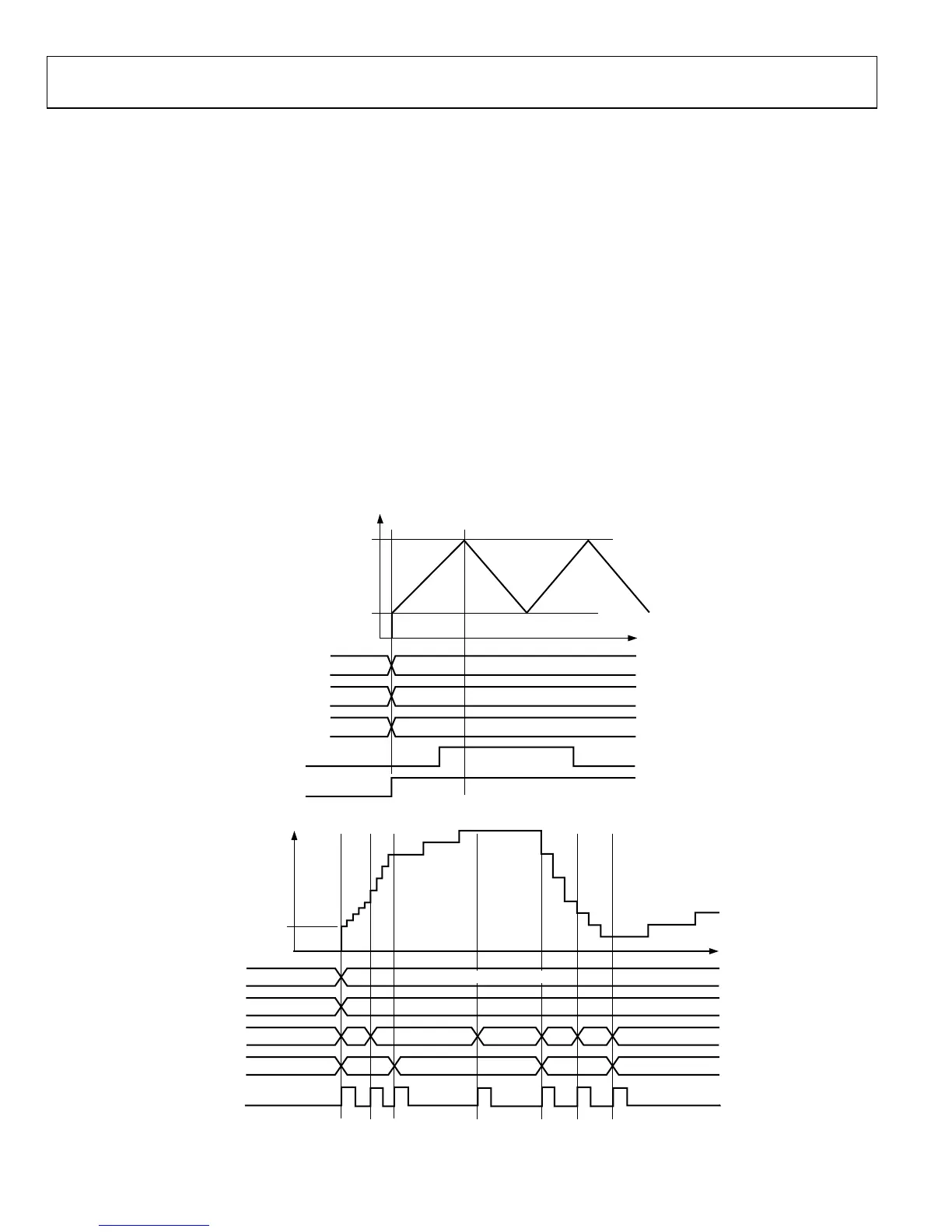
Nonlinear ramped FSK has the appearance of the chirp function
shown in
Figure 43. The difference between a ramped FSK
function and a chirp function is that FSK is limited to operation
between F1 and F2, whereas chirp operation has no F2 limit
frequency.
Two additional control bits (CLR ACC1 and CLR ACC2) are
available in the ramped FSK mode that allow more options. If
CLR ACC1 (Register Address 1F hex) is set high, it clears the
48-bit frequency accumulator (ACC1) output with a retriggerable
one-shot pulse of one system clock duration. If the CLR ACC1
bit is left high, a one-shot pulse is delivered on the rising edge of
every update clock. The effect is to interrupt the current ramp,
reset the frequency to the start point (F1 or F2), and then continue
to ramp up (or down) at the previous rate. This occurs even when
a static F1 or F2 destination frequency has been achieved.
Alternatively, the CLR ACC2 control bit (Register Address 1F
hex) is available to clear both the frequency accumulator
(ACC1) and the phase accumulator (ACC2). When this bit is
set high, the output of the phase accumulator results in 0 Hz
output from the DDS. As long as this bit is set high, the
frequency and phase accumulators are cleared, resulting in 0 Hz
output. To return to previous DDS operation, CLR ACC2 must
be set to logic low.
Chirp (Mode 011)
This mode is also known as pulsed FM. Most chirp systems use
a linear FM sweep pattern, but the AD9854 can also support
nonlinear patterns. In radar applications, use of chirp or pulsed
FM allows operators to significantly reduce the output power
needed to achieve the result that a single-frequency radar
system would produce.
Figure 43 shows a very low resolution
nonlinear chirp, demonstrating the different slopes that are created
by varying the time steps (ramp rate) and frequency steps (delta
frequency word).
F2
F1
0
FREQUENCY
MODE
TW1
TW2
FSK DATA
RIANGLE BIT
000 (DEFAULT)
0
0
010 (RAMPED FSK)
F1
F2
00636-042
Figure 42. Automatic Linear Ramping Using the Triangle Bit
F1
0
FREQUENCY
010 (RAMPED FSK)
F1
000 (DEFAULT)
0
MODE
TW1
DFW
R
MP RATE
I/O UD CLK
00636-043
Figure 43. Example of a Nonlinear Chirp
 Loading...