AD9854
Rev. E | Page 9 of 52
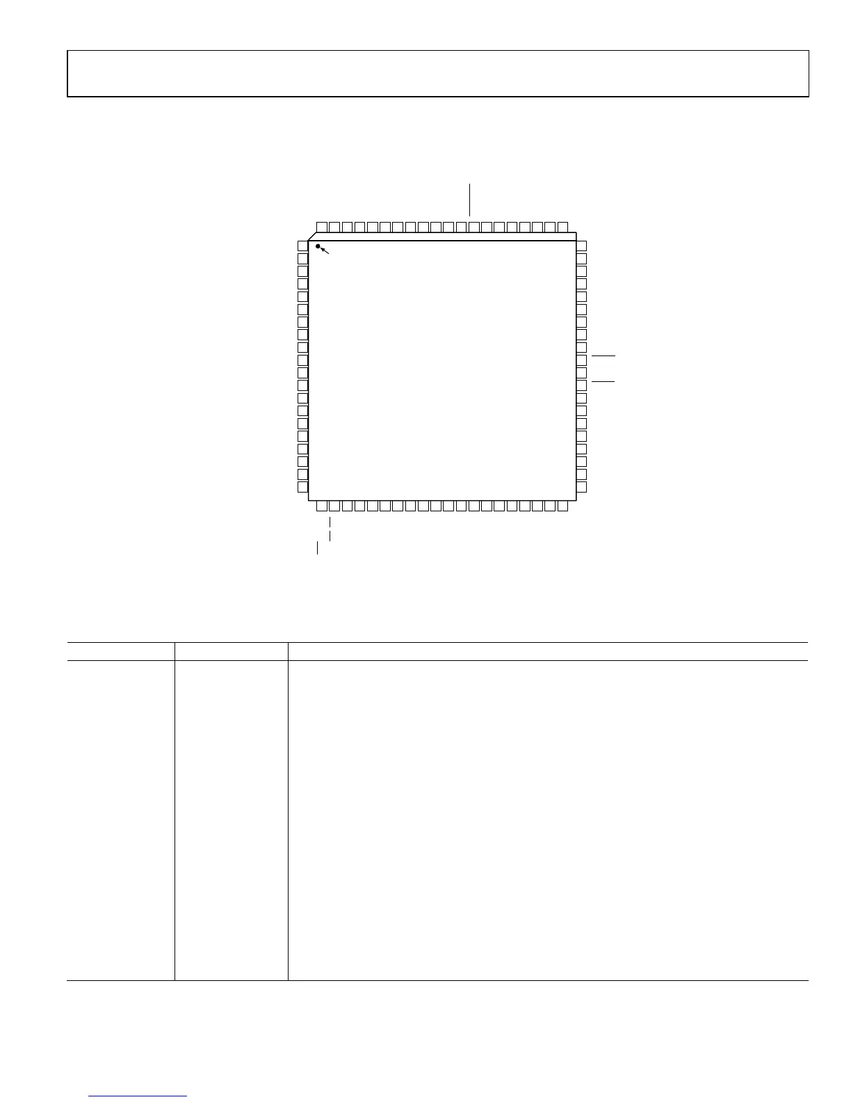
PIN CONFIGURATION AND FUNCTION DESCRIPTIONS
80 79 78 77 76 71 70 69 6875 74 73 72
21 22 23 24 25 26 27 28 29 30 31 32 33
1
2
3
4
5
6
7
8
9
10
11
13
12
60
59
58
57
56
55
54
53
52
51
50
49
48
NC = NO CONNECT
AD9854
TOP VIEW
(Not to Scale)
WR/SCLK
RD/CS
DVDD
DVDD
DVDD
DGND
DGND
DGND
FSK/BPSK/HOLD
OSK
AVDD
AVDD
AGND
DVDD
DVDD
DGND
DGND
DGND
DGND
DVDD
DVDD
DGND
MASTER RESET
S/P SELECT
REFCLK
REFCLK
D7
D6
D5
D4
D3
D2
D1
D0
DVDD
DVDD
DGND
DGND
NC
AVDD
AGND
NC
NC
DAC R
SET
DACBP
AVDD
AGND
IOUT2
IOUT2
AVDD
IOUT1
IOUT1
PIN 1
INDICATOR
14
15
16
17
18
20
19
47
46
45
44
43
42
41
A5
A4
A3
A2/IO RESET
A1/SDO
A0/SDIO
I/O UD CLK
AGND
AGND
AGND
AVDD
VINN
VINP
AGND
64 63 62 6167 66 65
34 35 36 37 38 39 40
AGND
NC
VOUT
AVDD
AVDD
AGND
AGND
AGND
AGND
AVDD
DIFF CLK ENABLE
NC
AGND
PLL FILTER
00636-002
Figure 2. Pin Configuration
Table 4. Pin Function Descriptions
Pin No. Mnemonic Description
1 to 8 D7 to D0 8-Bit Bidirectional Parallel Programming Data Inputs. Used only in parallel programming mode.
9, 10, 23, 24, 25,
73, 74, 79, 80
DVDD
Connections for the Digital Circuitry Supply Voltage. Nominally 3.3 V more positive than AGND
and DGND.
11, 12, 26, 27, 28,
72, 75 to 78
DGND Connections for the Digital Circuitry Ground Return. Same potential as AGND.
13, 35, 57, 58, 63 NC No Internal Connection.
14 to 16 A5 to A3
Parallel Address Inputs for Program Registers (Part of 6-Bit Parallel Address Inputs for Program
Register, A5:A0). Used only in parallel programming mode.
17 A2/IO RESET
Parallel Address Input for Program Registers (Part of 6-Bit Parallel Address Inputs for Program
Register, A5:A0)/IO Reset. A2 is used only in parallel programming mode. IO RESET is used when
the serial programming mode is selected, allowing an IO RESET of the serial communication bus
that is unresponsive due to improper programming protocol. Resetting the serial bus in this
manner does not affect previous programming, nor does it invoke the default programming
values listed in
Table 8. Active high.
18 A1/SDO
Parallel Address Input for Program Registers (Part of 6-Bit Parallel Address Inputs for Program
Register, A5:A0)/Unidirectional Serial Data Output. A1 is used only in parallel programming
mode. SDO is used in 3-wire serial communication mode when the serial programming mode is
selected.
19 A0/SDIO
Parallel Address Input for Program Registers (Part of 6-Bit Parallel Address Inputs for Program
Register, A5:A0)/Bidirectional Serial Data I/O. A0 is used only in parallel programming mode. SDIO
is used in 2-wire serial communication mode.
 Loading...