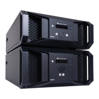
Starng from the Leader device, connect the SYNC OUT2 RJ45 connector of the unit to the SYNC IN2 of the
next unit.
IMPORTANT: when reaching the last unit, do not close the loop.
When properly connected, the orange LED (connecon speed) should be ON and the green LED (network
acvity) should be blinking.
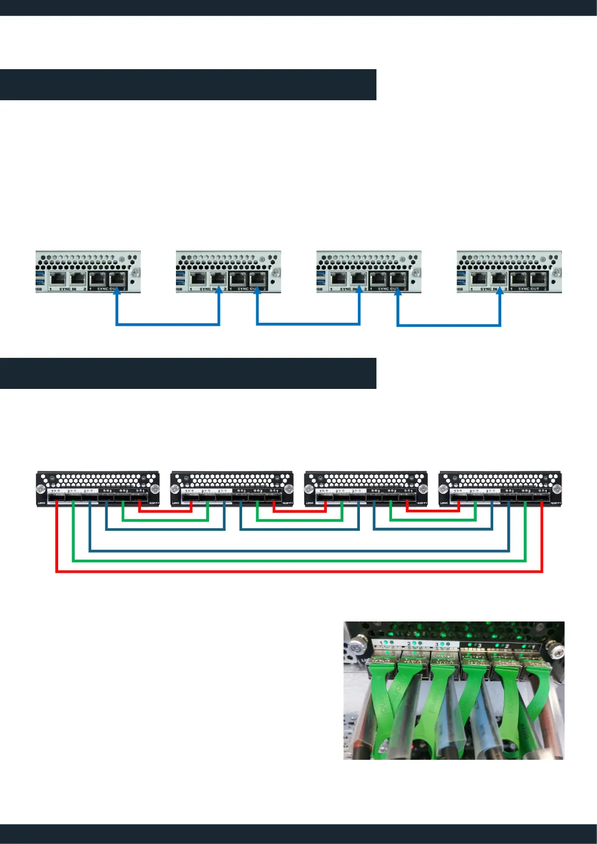
A link video ring must be created by connecng the QSFP outputs(black area) of each device’s Link connector
card to the QSFP inputs(white area) of the next device’s Link connector card.
IMPORTANT: Please carefully respect the numbering of the connector (OUT 1 to IN1, OUT 2 to IN 2 and OUT
3 to IN 3)
TIP: The DAC link cables are equipped with colored wrap label
with marking: RED / GREEN /BLUE. Always use the same color
with the same number: 1 = RED, 2 = GREEN, 3= BLUE
01-MAR-2024
LINK - QSG
 Loading...