Do you have a question about the ANCA Motion AMD2000 Series and is the answer not in the manual?
Adherence to safety precautions for equipment operators.
Guidelines for safe initial operation of the drive.
Outlines the manual's objective and target audience for planning and operation.
Provides an overview of the drive's capabilities and technology.
Lists applicable drive variants and their product numbers.
Defines technical terms and abbreviations used in the manual.
Details the standard features and capabilities of the AMD2000 drive.
Explains the basic circuit diagram and AC-to-DC conversion process.
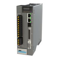
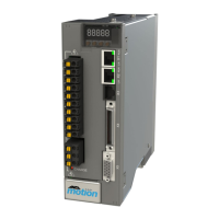
Shows how to identify different AMD2000 drive models.
Details connectors and pin assignments for drive models.
Checks to perform before installing the drive.
Specifies requirements for installation, tools, and environment.
Specifies requirements for the drive's installation environment.
Details mounting procedures and cooling considerations.
Procedures for installing and unmounting the drive.
Procedures for safely isolating power before installation.
Step-by-step guide for physically mounting the drive.
Ensures compatibility between motors and drives.
Guidance on selecting appropriate power and motor cables.
Recommendations for selecting control cables.
Guidelines for routing different types of cables to avoid interference.
Requirements for connecting to the main AC power supply.
Specifies acceptable input voltage ranges and frequencies.
Details RCD protection for insulation faults.
Explains the functions and requirements of the grounding system.
Discusses EMC compliance and interference reduction.
Recommended EMC filters for mains and control supply.
Instructions for connecting the servo motor and shielding.
Procedures for installing motor power cables with shielding.
Importance and methods for cable shielding.
Details on using sinusoidal and du/dt filters.
Explains sinusoidal filters and their applications.
Information on inbuilt and external brake/regeneration resistors.
Details analog input and output connections via connector X4.
Information on analog input circuitry and connections.
Details digital input and output signals available via connector X5.
Overview of digital input types and examples.
Details on the Ethernet interface and EtherCAT protocol.
Explanation of the EtherCAT protocol and its capabilities.
EtherCAT network configurations and port usage.
Details on connecting motor feedback devices.
Typical wiring diagram for digital incremental encoder cables.
A comprehensive checklist for safe and successful initial power-up.
Overview of ANCA MotionBench for inspection and commissioning.
Lists minimum PC requirements for MotionBench software.
Steps to configure the Ethernet adapter for PC connection.
Procedures for starting and performing power-on checks.
Procedures to follow during start-up for safe operation.
Step-by-step guide for installing the MotionBench software.
Guides on configuring the drive using MotionBench.
Adjusting raw SINCOS encoder signals for accurate feedback.
Adjusting position estimation to compensate for drivetrain backlash.
Using UVW encoders for Field Orientation Initialisation.
Configuring digital outputs for information or external actions.
Setting the drive status to appear operational when not actively controlling.
Synchronously sampling and logging data from drives.
Details on connecting and configuring encoder channels.
Aligning the rotor field angle for optimal motor performance.
Selecting different motion control approaches for the drive.
Parameters for restraining axis movements and monitoring behavior.
Details on implementing torque and current control for motors.
Pre-setting up to 8 drive modes of operation.
Configuring temperature sensors for motor and amplifier.
Using low-pass and notch filters for torque commands.
Guidance on diagnosing issues using drive indicators.
Explains the functions of the 7-segment LED display.
Display codes indicating EtherCAT communication status.
Overview of error code prefixes and severities.
Defines severity levels for error codes (E, W, I).
A summary list of error and warning codes.
Detailed explanations of error codes and their causes.
Lists error codes related to firmware upgrades.
Lists drive control functions and modes.
Lists available control modes for the drive.
Details thermal limits and over-current protection.
Lists advanced control functions supported by the drive.
Details specifications for I/O, encoders, and communication interfaces.
Specifications for the 24V digital inputs.
Specifications for the 24V digital outputs.
Information on motor position feedback channels and encoders.
Specifications for encoder channel 1.
Specifications for the Ethernet interface.
Details on power supply and digital servo drive specifications.
Key electrical specifications for the digital servo drive.
Details on resolution, dynamic performance, and braking.
Details settling time and current loop response.
Information on regenerative braking switching capacity and resistors.
Details on storage, transport, installation, and operating conditions.
Environmental conditions for installation and operation.
Dimensions, weight, and degree of protection.
Physical dimensions and mounting hole positions for drives.
Detailed dimensions for the AMD2000 3A drive.
How input voltage affects DC bus ripple.
De-rating characteristics for the AMD2000 3A drive.
Information on inbuilt and external brake/regeneration resistors.
Calculations for selecting brake resistors based on energy and power.
Lists standards conformity for the drive.
Information on motors and their catalogue number interpretation.
Explains how to interpret motor catalogue numbers.
Table of electrical specifications for motors.
Information on cable catalogue number interpretation and types.
Explains how to interpret cable catalogue numbers.
Details on available encoder cables.
Lists other available accessories.
Details I/O interface modules and cables.
Lists components of the AMD2000 3A EMC Kit.
Lists components of the AMD2000 9A EMC Kit.
Information on starter kits.
Details the AMD2000 3A Starter Kit.
Guidance on maintenance and repair procedures.
Contact information for product support and service.
| Communication Interface | EtherCAT |
|---|---|
| Feedback | Resolver |
| Safety | STO (Safe Torque Off) |
| Control Modes | Velocity, Position |
| Protection Features | Overcurrent, Overvoltage, Undervoltage, Overtemperature |
| Cooling Method | Convection or forced air |