Do you have a question about the AND Weighing Indicator AD-4401 and is the answer not in the manual?
Details technical specifications of the A/D converter.
Details technical specifications of the digital display and control.
Lists overall technical specifications, including I/O.
Lists included accessories and their part numbers.
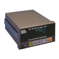
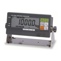
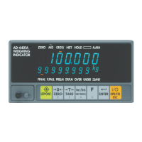
Describes the front panel layout and its components.
Details the various weighing capabilities of the instrument.
Describes the rear panel layout and its connectors.
Describes the top section of the front panel.
Details installation environment requirements and precautions.
Provides instructions for connecting the power supply.
Details load cell connection procedures and recommendations.
Explains the different operating modes of the instrument.
Outlines procedures to confirm operations after unpacking and calibration.
Describes methods for setting setpoints for weighing sequences.
Details setting setpoints using front panel keys.
Details setting setpoints using a 5-digit thumbwheel switch.
Details setting setpoints using a 16-digit thumbwheel switch.
Provides an overview of calibration modes.
Details the procedure for calibrating with actual weights.
Explains setting basic constants for calibration.
Lists common calibration errors and their causes/solutions.
Describes how to initialize all data to factory settings.
Details basic functions and capabilities of the instrument.
Details functions related to weighing sequences.
Describes the functions of control I/O input terminals.
Describes the functions of control I/O output terminals.
Provides a general overview of weighing sequences.
Details the customer programmed control mode for batch weighing.
Explains the built-in automatic program mode for batch weighing.
Provides details on using thumbwheel switches for batch weighing.
Details the check weighing modes and their output conditions.
Explains how comparison weight is used.
Describes the auto print function for outputting data.
Details the automatic accumulation function.
Explains automatic free fall compensation to reduce loading error.
Details fuzzy logic application for automatic free fall compensation.
Describes the control I/O for external signals.
Details the functions of input terminals A1 through A6.
Details the functions of output terminals B1 through B8.
Explains how to set setpoints using thumbwheel switches or external input.
Describes the standard serial output interface.
Details the OP-01 parallel BCD output option.
Describes the OP-03 RS-422/-485 interface option.
Details the OP-04 RS-232C input/output option.
Describes the OP-05 setpoint unit for batch weighing.
Details the OP-07 analog output option for sending weight data.
Explains how to enter and use the check mode for maintenance.
Describes the three initialization modes for returning to factory values.
Provides a list of general functions and their settings.
| Model | AD-4401 |
|---|---|
| Display Type | LCD |
| Operating Temperature | 0 to 40°C |
| Display | 7-segment |
| Communication Interface | RS-232 |
| Storage Temperature | -10°C to 50°C |
| Humidity | 85% RH or less (no condensation) |
| Load cell input voltage | 10V |
| Digital Interface | RS-232 |
| Power Supply | 100-240V AC, 50/60Hz |