EasyManua.ls Logo

AND AD-4401A User Manual

AND AD-4401A
100 pages
To Next Page IconTo Next Page
Page #1 background imageLoading...
Page #1 background image
AD-4401A
Weighing Indicator
INSTRUCTION MANUAL
1WMPD4003050F

Table of Contents

Question and Answer IconNeed help?

Do you have a question about the AND AD-4401A and is the answer not in the manual?

AND AD-4401A Specifications

General IconGeneral
BrandAND
ModelAD-4401A
CategoryAccessories
LanguageEnglish

Summary

1. Safety Precautions

Precautions on Designing and Installation

Safety circuit and environmental requirements for safe installation.

Precautions on Wiring

Wiring safety guidelines including grounding and cable placement.

4. Connection to Power Supply

AC Power Input Terminals

Terminal assignment and connection diagram for AC power input.

5. Connection to Load Cell

Load Cell Terminal Assignment and Diagram

Terminal assignment and connection diagrams for load cell input.

6. Calibration

Calibration Settings

Configuration of unit, decimal point, capacity for calibration.

Calibration Using Weights

Step-by-step procedure for zero and span calibration.

Error List

8. Batch Weighing Functions

Normal Batching Explained

Details weighing start, feeding, and end processes for normal batching.

Loss-in-Weight Batching Explained

Details weighing start, feeding, end processes, and near-zero/full conditions.

Sequential Weighing Functions

Explains auto free fall correction, accumulation, print, stop, errors.

9. Check Weighing Functions

Check Weighing Stages 1-3

Defines control outputs for five stages of check weighing.

Check Weighing Stage 4

Defines control outputs for five stages of check weighing.

10. Control I/O

10.1. Pin Assignment

Shows pin layout and assignments for the Control I/O connector.

10.2. Connection Diagram

Illustrates control input and output circuit diagrams.

11. Setpoint Input

11.1. Pin Assignment

Shows pin layout and assignments for setpoint input.

Setpoint Pin Assignments by Mode

Details pin assignments for various weighing modes and input methods.

11.2. Connection Diagram

Illustrates the connection diagram for setpoint input.

12. Standard Serial (Current Loop) Output

12.1. Pin Assignment & Specs

Pin layout, assignments, and communication specifications for serial output.
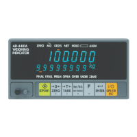
13. Option-01 BCD Output

14. Option-03 RS-422/485

14.10. Modbus-RTU Communication

15. Option-04 RS-232C

16. Option-07 Analog 4-20mA Output

17. Option-23 Modbus-TCP

18. Setpoint Setting

19. Operation Checking

20. Initialization

Related product manuals