EasyManua.ls Logo

Anderson Greenwood Series User Manual

Anderson Greenwood Series
16 pages
To Next Page IconTo Next Page
Page #1 background imageLoading...
Page #1 background image
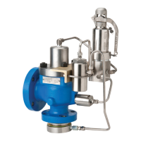
ANDERSON GREENWOOD SERIES 5200 POSRV
InstallatIon and MaIntenance InstructIons
Before installation these instructions must be fully read and understood
Engineering doc nr. 05.9040.370 Rev. D
Emerson.com/FinalControl © 2017 Emerson. All Rights Reserved. VCIOM-02850-EN 18/02
TABLE OF CONTENTS
1. General valve description and start-up ....... 1
2. Main valve maintenance ............................... 2
3. Pilot maintenance ......................................... 8
4. Accessories maintenance........................... 10
5. Valve assembly ............................................ 12
6. Pilot pre-set pressure adjustment ............ 12
7. Valve assembly testing................................ 13
8. Pilot set pressure field test procedure ...... 15
9. Soft goods repair kits .................................. 16
1 GENERAL VALVE DESCRIPTION AND
START-UP
1.1 Operation
The Series 5200 valve is designed for ASME
Section I economizer and ASME Section VIII
steam service. The valve has modulating
action; the main valve will open at nameplate
set, but only opening an amount proportional
to the relieving capacity required. As process
pressure increases, the valve will open more
and be in full lift at 103% of set.
The main valve uses the principle of differential
areas between the main valve dome and seat
to hold the disc closed up to set pressure. At
set pressure, the pilot relieves, depressurizing
the volume on the top side/dome of the piston.
1.2 Installation
Both the inlet and outlet have standard ANSI
flanges that should be installed in accordance
with accepted piping practices. For Section I
economizer applications, the valve is supplied
with a body drain fitting, which should be piped
away to a condensate collection system. For
Section VIII applications, a body drain fitting is
not available.
The valve can be insulated and/or heat traced
to prevent freezing of condensate in the valve
or tubing. The main valve cap must not be
insulated as this will obstruct the convection
cooling process that keeps the main valve
dome filled with condensate. Refer to Anderson
Greenwood Crosby Procedures #05.9040.352
(VCIOM-06043 Installation and Start-up
Instructions) and #05.9040.372 (Winterization
Guidelines) for more information regarding
winterization requirements.
This valve can be plumbed for internal or
remote sense (see Figure 1). For internal
sense, a sense ring with a pitot tube is installed
between the valve and process flange and the
pitot tube port in the sense ring is plumbed to
the pilot supply port. For remote sense, the
sense ring is not required and the pilot supply
port can be plumbed to a remote location
on the process piping. Remote pressure
pick-up piping up to 100 feet [30 m] in
length must have an inside diameter not
less than 0.245" [6 mm], which is the same
as the inside diameter of ⅜"x 0.065" wall
[10 mm x 2 mm wall] seamlesstubing.
Line pressure acting on the underside of the
disc causes the disc to lift, permitting discharge
from the main valve. As capacity relief of the
system is satisfied, system pressure will begin
to decrease. When it does, the pilot will actuate
and direct system pressure to the top side of
the main valve piston, closing the disc against
the nozzle.
The pilot is a non-flowing type. With the main
valve open and relieving at steady pressure,
no process fluid flows through the pilot. When
process pressure changes, the pilot actuates to
change the lift of the main valve piston. During
these actuations a small amount of fluid from
the main valve dome flows through the pilot
and is discharged through the pilot exhaust.
For lengths greater than 100 feet [30m],
larger tubing or pipe should be used. For
greater mechanical integrity of a remote sense
line, consider using a minimum ¾" pipe size
for remote sense line longer than 20 feet,
transitioned to ⅜" tubing near the POSRV. The
remote sense line should be self draining or
winterized, as required.
Question and Answer IconNeed help?

Do you have a question about the Anderson Greenwood Series and is the answer not in the manual?

Anderson Greenwood Series Specifications

General IconGeneral
BrandAnderson Greenwood
Orifice SizeD to T
SeriesSeries 90
CategoryPressure Relief Valves
Set Pressure Range6000 psig
Pressure RangeUp to 6000 psig
MaterialsStainless Steel, Carbon Steel, Alloy Steel
Connection TypeFlanged, Threaded
CertificationsASME, PED
StandardsAPI 526

Summary

General Valve Description and Start-up

1.1 Operation

Explains the modulating action and differential areas principle for valve operation.

1.2 Installation

Covers flange installation, drain fittings, insulation, and remote sense line requirements.

Main Valve Maintenance

1.3 Start-up

Details the procedure for starting up the valve, including block valve operation and slow opening.

1.4 Maintenance

Introduces recommended maintenance procedures for pilot and main valves, emphasizing regular programs.

2.1 Main Valve Disassembly

Provides step-by-step instructions for disassembling the main valve, listing parts to remove and inspect.

2.2 Main Valve Seat Reconditioning

Details how to recondition valve seats through lapping, emphasizing flatness and compound use.

2.3 Main Valve Assembly

Provides instructions for assembling the main valve, including part installation and lubrication.

Pilot Maintenance

3.1 Pilot Disassembly

Provides detailed steps for disassembling the pilot valve, including part identification and removal.

3.2 Pilot Assembly and Lapping

Covers pilot assembly, lapping seat/nozzle, cleaning, sub-assembly, and lift lever installation.

Accessories Maintenance

4 Accessories Maintenance

Covers maintenance for condensate traps, check valves, and field test devices, including seal replacement.

Valve Assembly

5 Valve Assembly

Instructions for reassembling the pilot to the bracket and connecting tubing for the valve.

Pilot Pre-Set Pressure Adjustment

6.1 Definitions, Pilot Only

Defines key terms related to pilot pressure adjustment, such as set pressure and cracking pressure.

6.2 Set Pressure, Pilot Only

Describes the procedure for pre-setting and checking pilot set pressure using a test setup.

6.3 Range of Adjustment

Specifies the allowable adjustment range for pilot set pressure and when to consult the factory for spring changes.

6.4 Performance Requirements, Pilot Only

Lists performance requirements for the pilot, including crack pressure and set pressure tolerance.

Valve Assembly Testing

7.1 General Testing

Outlines general requirements for testing the complete valve assembly, specifying steam as the test medium.

7.2 Set Pressure Check

Details the procedure for checking the set pressure of the valve assembly by slowly increasing inlet pressure.

7.3 Leakage Check

Explains how to perform leakage checks on the valve seats and external joints at specified pressures.

7.4 Back Pressure Test

Describes the procedure for performing a back pressure test on the secondary zone of the valve.

7.5 Performance Requirements

Provides guidance on set pressure adjustment, blowdown, and minimum required lift for valve performance.

Pilot Set Pressure Field Test Procedure

8.1 General Field Test

Introduces checking set pressure with the valve installed in service using a field test accessory.

8.2 Field Test Procedure

Provides step-by-step instructions for conducting the pilot set pressure field test using a test setup.

Soft Goods Repair Kits

9.1 Pilot Repair Kit

Lists the part number for the pilot repair kit.

9.2 Main Valve Repair Kits

Provides a table of part numbers for main valve repair kits based on orifice size and flange rating.