2. Strip back 1-1/4” of outer sheathing, cut off any excess
wires, shield and ground. Strip off 1/4” insulation from
remaining four wires. It is not necessary or recommended
1. Insert cable through Pressing Screw, Compression
Ring, Seal Grommet, and Sleeve as shown below.
CABLE REQUIREMENTS
4 conductor, stranded, 18-24 AWG,
shielded with ground.
4-8mm (0.16-0.31”) Cable Sheath
OD.
Shown With
Cap Removed
3. Orient Connector end so that
center pin connecting screw is
horizontal facing right (see
detail).
4. Wire PWR + (red) wire to top-right
terminal, and PWR - (black) wire to
top-left terminal. Wire LOOP + (white) to
center terminal and LOOP - (green) to
bottom left terminal.
5. Screw on the Sleeve. Hand-tighten only.
6. Press the Seal Grommet into the Sleeve and
hand-tighten the Pressing Screw against the
compression ring.
7. Use a wrench to tighten the Pressing Screw
another 3/4 turn. Do not over-tighten!
Connector End
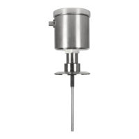
Section 1 - Field Wireable Connector
LN Potentiometric Level Transmitter
Quick Start Installation Guide
Rev. 2.1 Doc 1136 Page 1 of 2
Technical Bulletin
Anderson Instrument Co., Inc.
156 Auriesville Road
Fultonville, NY 12072
Phone: 518-922-5315 or 800-833-0081
www.anderson-negele.com
To install connector, simply line up key, press
into receptacle, and hand-tighten the
*Receptacle pins should be coated with
USDA approved dielectric grease to
Minimize possibility of corrosion.
Field Wireable Connector
+PWR (red) wire
-PWR (black) wire
Shield (clear or bare) wire
P/N: 42119B0000 (without cable)
P/N: 5662400000
*Dielectric Grease
Retaining Ring
Pin 1 - Red
(+PWR 18-36 VDC)
Pin 2 - Black
(-PWR)
DETAIL
Sleeve
Seal
Grommet
Compression
Ring
Pressing Screw
-2 included choose one to accommodate cable OD
Pin 3 - Green
(LOOP- Return)
Pin 5 - White
(LOOP+)
Loop- return (green) wire
Loop+ (white) wire
Molded Cord Set - Heavy Duty
P/N: 42117F0025
42117F0050
42117F0100
Loop + (grey) wire
Loop - (blue) wire
Shield (clear or bare) wire
PWR- (white) wire
PWR+ (brown) wire
Molded Cord Set
Note: Green and White not used
on 2 wire devices.
Shield not connected to nut.
P/N: 42117K0025
42117K0050
42117K0100
+PWR (red) wire
-PWR (black) wire
Shield (clear or bare) wire
Loop- return (green) wire
Loop+ (white) wire