EasyManua.ls Logo

Angelo Po 0N1CP1GH - User Manual

Angelo Po 0N1CP1GH
116 pages
Go to English
Print Icon
To Next Page IconTo Next Page
Loading...
0N1CP1GH
0T1CP1GH
1N1CP2GH
1T1CP2GH
CUOCIPASTA
GPASTA COOKER
NUDELKOCHER
CUISEUR À PÂTES
COCEDOR DE PASTA
ISTRUZIONI PER L’UTILIZZATORE
USE MANUAL
BEDIENSHANDBUCH
MANUEL D’UTILISATION
MANUAL DE USO
IT
GB
DE
FR
ES
Italiano
English
Deutsch
Français
Español
Rev.2 11/2017
3269830
Leggere attentamente le istruzioni prima di installare e utilizzare l’apparecchiatura.
Read the instructions carefully before installing and using the appliance.
Vor der Installation und Nutzung des Geräts müssen die Anleitungen aufmerksam durchgelesen werden.
Lire attentivement les instructions avant d’installer et d’utiliser l’appareil.
Léanse atentamente las instrucciones antes de instalar y utilizar el aparato.
Il mancato rispetto delle istruzioni fa decadere la garanzia del fabbricante.
In the event of failure to comply with the instructions, the manufacturer’s warranty shall cease to apply.
Die Missachtung der Anleitungen hat den Verfall der vom Hersteller gewährten Garantie zur Folge.
Le non respect des instructions entraîne l’invalidation de la garantie du fabricant.
La inobservancia de las instrucciones provoca la invalidación de la garantía otorgada por el fabricante.

Table of Contents

Question and Answer IconNeed help?

Do you have a question about the Angelo Po 0N1CP1GH and is the answer not in the manual?

Overview

This document describes the pasta cooker, referred to as the appliance, designed and constructed for cooking pasta in water within the professional catering sector. The appliance is available in several versions to meet varying user requirements.

Important Technical Specifications:

The appliance's identification plate, affixed directly to the equipment, provides essential information for operating safety. Key data includes:

  • Appliance Model: (b1)
  • Manufacturer Identification: (b3)
  • Serial Number: (b4)
  • Protection Class: (b5)
  • EC Conformity Mark: (b6)
  • Rated Power: (b11) in kW
  • Gas Consumption: (b12)
  • Voltage: (b14) in V
  • Frequency: (b15) in Hz
  • Electricity Power Consumption: (b16) in W
  • Date of Construction: (b18)

For gas supply, the plate specifies:

  • Country of Use: (a1)
  • Appliance Category: (a2)
  • Type of Gas: (a3), (b10), (c1)
  • Gas Pressure: (a4), (c2)
  • Type of Fume Exhaust Vent: (a5)
  • Testing Gas Indicator Frame: (b13)

Water connection characteristics for potable water:

  • Pressure: 200÷400 kPa (2÷4 bar)
  • pH: 7÷8.5
  • TDS: 40÷150 ppm
  • Hardness: 3÷9°f (1.5÷5°d, 2.1÷6.3°e, 30÷90 ppm)
  • Langelier Index (recommended): >0.5
  • Content of salts and metal ions (Requested): Chlorine <0.1 mg/l, Chlorides <10 mg/l, Sulphates <30 mg/l
  • Content of salts and metal ions (Recommended): Iron <0.1 mg/l, Copper <0.05 mg/l, Manganese <0.05 mg/l
    • Note: Values different from these parameters may cause corrosion if combined with wrong use and environment.

The appliance is supplied with an operating voltage of 230V/1N 50Hz (60Hz permissible).

Usage Features:

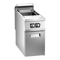
The main parts and controls of the pasta cooker are:

  • Cooking Well (A): The main tank for cooking.
  • Fume Exhaust Vent (B): For removing combustion fumes from the burner.
  • Mains Light (C): Indicates when the appliance is receiving electrical power.
  • Safety Indicator Light (D): Illuminates if the water level in the tank drops below the minimum.
  • Adjustable Water Spout (E): Directs the flow of water.
  • Water Control Knob (F): Used for filling the well in various modes.
  • Power Level Knob (G): Adjusts heating intensity to one of three levels.
  • Burner Control Knob (H): For lighting, turning off, and regulating the burner and pilot light.
  • Water Drain Lever (L): Drains water from the well.

Switching On and Off:

  1. Activate the main electrical connection via the master switch.
  2. Open the water supply tap.
  3. Open the gas supply tap.
  4. Before filling, ensure the drain lever is in "CLOSED" position.
  5. Turn the water control knob (A) clockwise to position 3 for automatic filling to the maximum level. The mains light (C) will turn off.
  6. Press and turn the burner control knob (E) anti-clockwise to position 1 to light the pilot light. Hold for approximately 15 seconds for the thermocouple to activate.
  7. Press and turn the burner control knob (E) anti-clockwise to position 2 to light the main burner.
  8. Turn the power level knob (B) to one of the other positions (e.g., position 5) to adjust burner intensity.

To turn off:

  1. Turn the power level knob (B) anti-clockwise to position 2 to cut off electrical supply.
  2. Turn the water control knob (A) anti-clockwise to position 1 to stop water delivery.
  3. Press and turn the burner control knob (E) clockwise to position 3 to turn off the burner. The pilot light remains on for subsequent ignitions.
  4. Press and turn the burner control knob (E) clockwise to position 4 to turn off the pilot light.
  5. Close the gas and water supply taps and switch off the main electricity supply.
    • Important: Drain the well completely after use.

Filling and Emptying the Well:

  • Automatic Quick Filling: Turn water control knob (A) to position 1. Fills automatically to max level when water drops below minimum.
  • Slow Automatic Top-up: Turn water control knob (A) to position 2. Provides a slow, continuous flow to maintain constant water level. If water drops below minimum, quick automatic top-up is triggered.
  • Quick No-Limits Filling: Turn water control knob (A) to position 3. Fills to desired level.
    • Important: After filling, turn knob (A) to another position to prevent overflow.
  • Emptying: Turn water control knob (A) to position 4 to stop water supply. Turn water drain lever (B) to "OPEN" to drain the well.
    • Caution: Never use the appliance without water in the well to avoid damage.

Lengthy Downtimes:

  1. Turn off gas and main electricity supply.
  2. Turn off water supply tap.
  3. Clean appliance and surrounding areas thoroughly.
  4. Spread a thin film of edible oil on stainless steel surfaces.
  5. Perform all servicing procedures.
  6. Cover the appliance, leaving gaps for air circulation.
    • Important: Drain and clean the well completely after use.

Maintenance Features:

Regular maintenance is crucial for optimal performance, extended lifespan, and consistent safety.

  • Daily Checks: Ensure safety devices are properly installed and functioning.
  • After Each Use: Clean the cooking well, accessories, and the appliance/surrounding area.
  • Every 100 Operating Hours: Skilled and authorized personnel must perform:
    • Gas pressure and system tightness check.
    • Safety thermocouple efficiency check.
    • Electrical system efficiency check.

Cleaning Instructions:

  • Before cleaning, always close the gas supply tap, cut off electricity, and allow the appliance to cool.
  • Use only warm water, food-approved detergents, and non-abrasive materials.
  • Thoroughly clean all parts in direct or indirect contact with food, and all surrounding areas.
  • Clean accessories with a suitable grease-remover; dishwasher cleaning is recommended.
  • Caution: Do not use products containing harmful or hazardous substances (solvents, petroleum spirits, etc.).
  • Rinse surfaces with drinking water and dry.
  • Use pressurized water jets only on external parts.
  • Be careful not to damage stainless steel surfaces; avoid corrosive products, abrasive materials, or sharp tools.
  • Remove food residues immediately to prevent hardening.
  • Clean limescale deposits.
  • Caution: When using detergents, wear rubber gloves, protective mask, and safety goggles.

Adjustments:

  • Adjustments are only required if the gas type differs from the factory test gas.
  • Must be performed by authorized, qualified personnel.
  • Before any adjustment, activate all safety devices and inform personnel. Close gas and water taps, disconnect electricity, and prevent access to devices that could cause unexpected hazards.
  • Adjusting Burner Primary Air: Involves opening the hatch, removing the drain lever and panel, loosening a screw, adjusting a ring nut to a specified distance (F) based on gas family, tightening the screw, sealing with paint, and reassembling.

Replacing Parts:

  • Only original spare parts should be used. Unauthorized modifications or use of non-original parts will void the CE marking and warranty.
  • Before any replacement, activate all safety devices and inform personnel. Close gas and water taps, disconnect electricity, and prevent access to devices that could cause unexpected hazards.
  • Burner Nozzle Replacement: Involves opening the hatch, removing the drain lever and panel, unscrewing the nozzle, replacing it with the correct one for the gas type, and reassembling.
  • Pilot Light Injector Replacement: Similar to burner nozzle replacement, but involves unscrewing a fitting and replacing the pilot light nozzle.

Equipment Decommissioning, Demolition, and Disposal:

  • Decommissioning procedures must ensure the appliance and its components are not a hindrance and are easily accessible.
  • All energy sources (electricity, etc.) must be disconnected and rendered unusable.
  • Any liquids (lubricants, fluids, etc.) must be drained.
  • Place the appliance in a suitable, inaccessible area with barriers.
  • When scrapping, sort all components by chemical characteristics and dispose of them separately according to legal requirements.
  • Important: Do not dump non-biodegradable products, lubricating oils, and non-metallic components (rubber, PVC, resins, etc.) in the environment. Dispose of them in compliance with relevant laws.

Angelo Po 0N1CP1GH Specifications

General IconGeneral
BrandAngelo Po
Model0N1CP1GH
CategoryCookers
LanguageEnglish