2-2 MA25400A mmWave Module and Bracket MA25400A mmWave Module
2-4 PN: 10410-00311 Rev. H VectorStar ME7838 Modules RM
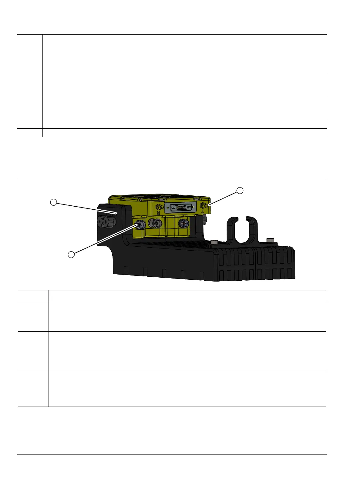
Alternate Configuration
If required, the module can be turned over for different 0.6 mm flange connector access as shown in Figure 2-4.
9
SRC Connector
To tighten, use an 8 mm (5/16”) torque end wrench set to 0.9 Nꞏm (8 lbfꞏin).
Recommended is Anritsu 01-201.
10
RF V Connector
• To tighten, use an 8 mm (5/16”) torque end wrench set to 0.9 Nꞏm (8 lbfꞏin).
• Recommended is Anritsu 01-201.
11
REF SSMC Connector
• To tighten, use a 4 mm (5/32 in) torque end wrench set to less than 0.17 Nꞏm (1.5 lbfꞏin).
• Recommended is Anritsu 01-529-R torque wrench.
12 Factory Calibrated Port Assignment Label
13 Module Serial Number Label
Index Description
1 The module can be mounted in an alternate position by removing the knurled thumbscrews and turning
the module upside down.
• In this orientation, the 0.6 mm flange connector is farthest from the top of the bracket.
• For ease of connection, attach the cables before mounting the module in the bracket.
2 Before attaching the module to the bracket, connect to the bottom row of connectors first, starting with
the middle and using torque factors described above:
•RF
•SRC
•LO
3 Connect the top row of connectors left and right side, the middle. Use the torque factors described
above:
•REF
• Power/Signal
•TEST
Figure 2-4. MA25400A mmWave Module – In Bracket – Alternate Module Orientation
Figure 2-3. MA25400A mmWave Module Description (2 of 2)
2
3
1