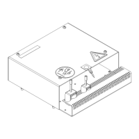
The FU Amplifier AS is a central component of the rudder control system, designed to control the hydraulic valves of the steering gear until the rudder's actual value matches the set value. It is available in two main types: 139-158.NG001 E01 and 139-158.NG002 E01, with an additional variant 139-158.SA001 E01.
Function Description
The FU Amplifier AS operates by receiving rudder set information via a dual CAN bus system from input devices such as a tiller, handwheel, or autopilot (when connected through a Steering Interface AS). This dual CAN bus provides redundancy within the steering control system. Actual rudder position information is transmitted to the FU Amplifier AS via a single CAN bus from a Rudder Feedback Unit AS.
The amplifier compares the set rudder value with the actual rudder position. The difference between these values acts as a controller difference, activating the switching outputs to control the pump valves of the rudder machine in an ON/OFF mode. Depending on the sign of this difference, either the port or starboard valve of the pump is opened. Both channels are activated synchronously, and the outputs remain active until the difference is balanced.
The FU Amplifier AS supports two primary operation modes:
- Follow-Up (FU) Mode: In this mode, the amplifier continuously compares the set rudder value with the actual rudder position and adjusts the pump valves to eliminate any difference.
- Non-Follow-Up (NFU) Mode: Here, control signals from an NFU Tiller are passed directly to the pump valves, bypassing the comparison logic.
The device also incorporates several features to ensure stable and precise rudder control:
- Dead Band: This feature prevents unstable (hunting) rudder actions by defining a range around the set rudder position where no action is taken. The dead band settings are configurable and dynamically adapted.
- Rudder Lead: For rudder machines with significant delay, this parameter can be activated to switch off the valves before the set value is achieved, compensating for the delay. Its adaptation depends on the status of pump 1 and pump 2, and the tune is aligned to the delay.
- Rudder Stop: In case of a failure (e.g., wire break), this function maintains the actual rudder position by disabling switching outputs and stopping analog outputs.
- Analog Output Modes: The analog set rudder outputs can be configured in Trans Mode, Diff Mode, or Sin/Cos Mode.
- Trans Mode: The set rudder output is scaled to a voltage value corresponding to the requested rudder position. Amplification is adjustable from 0.1 to 10, and both channels are controlled synchronously. In a rudder stop fail, the actual rudder position is fixed.
- Diff Mode: The difference between set rudder and actual rudder is calculated and output as an analog value. Amplification is adjustable from 0.1 to 10, allowing tuning of the rudder control loop for optimal performance. In a rudder stop fail, the control difference is set to zero, and the actual rudder position is maintained.
- Sin/Cos Mode: One set rudder output is scaled in sine voltage, and the other in cosine voltage, suitable for 360° azimuth steering.
The normal operations of the FU Amplifier AS are dependent on peripheral systems and devices, including FU tiller, NFU tiller, handwheel or autopilots, Steering Interface AS, Rudder Feedback Unit AS, and a stable power supply.
Important Technical Specifications
- Dimensions: Height 235 mm, Width 220 mm, Depth 75.5 mm.
- Weight: Approx. 2.5 kg.
- Protection Class: IP 12.
- Operation Temperature: -15 °C to +55 °C.
- Compass Safe Distance: Standard: 0.7 m, steering: 0.45 m.
- Power Consumption: Approx. 3 W.
- Voltage Supply:
- NG001: 230 V AC or 380 to 460 V AC +6% -10% (±15% for max. 3 seconds) 47.5 to 63.0 Hz.
- NG002: 115 V AC or 230 V AC.
- Outputs:
- 24 V DC (Plug B4): 18 to 31 V DC (maximum), 9 W (maximum). Used to supply Rudder Feedback Unit AS and set rudder steering components.
- Analog (set rudder) (Plugs B5, B6): ±10 V DC, 5 mA.
- Valve control (Plugs B14, B34): 24 V DC, 2 A (maximum).
- Inputs:
- Supply voltage (Plugs B1, B2): Configurable based on the device type (NG001 or NG002).
- Status information (Plug B13): Ri = 5 kΩ.
- CAN bus (Plugs B7, B8, B9): According to Anschütz dual CAN bus specification. Input load (status contacts): 24 V, Imax. 5 mA. Output load (status/alarm contacts): 30 V, Imax. 1 A.
Usage Features
The FU Amplifier AS is configured via a menu structure accessible on a PCB display using pushbuttons. This allows for setting various parameters:
- Rudder Scale: Sets the maximum rudder angle from 30° to 75° in 5° increments (default 35°).
- Dead Band: Configures DEADBAND 1 (pump 1 only), DEADBAND 2 (pump 2 only), and DEADBAND 1/2 (both pumps) from 0.2° to 2.6° in 0.1° increments (default 1.2°).
- Rudder Pulse: For service personnel, sets the duration of the rudder pulse from 0.0 to 1000.0 s in 20.0 s increments (default 0.0 ms).
- Rudder Lead: Compensates for rudder machine delay, adjustable from 0 to 10 in increments of 1 (default 0). Separate settings for pump 1, pump 2, and both pumps.
- Analog Gain: Configures the gain for analog outputs from 0.01 to 10.0% in 0.04% increments (default 1.00%). Separate settings for ANALOG GAIN OUTPUT 1 and 2.
- Steering Fail Monitoring: Sets a THRESHOLD (1° to 20° in 1° increments, default 0° for OFF) and a DELAY (0 to 20 s in 1 s increments, default 0 s) for triggering a steering fail alarm.
- Alarm List: Displays active faults and error log entries, with time information if UTC is available, or an operation counter otherwise.
- Show Settings: Displays configured values, actual steering values, and general system information, including serial number, type info, remarks, description, steering mode, rudder assignment, channel for pump control, and software version.
- BITE / FRAM: Allows testing internal functions and storing default settings to Ferroelectric Random Access Memory (FRAM).
- Rudder Com: Activates rudder movement to port or starboard for testing and optimizing steering performance.
Maintenance Features
- Self-Diagnosis (BITE): The Built-In Test Equipment (BITE) function can be initiated to check internal functions. It indicates "BITE OK" if no faults are detected or "DAC1 ERROR" / "DAC2 ERROR" if voltage faults are present at the digital-to-analog converter.
- Error Log: The device maintains an error log that records failure messages in sequence, along with time information, aiding in troubleshooting. Possible entries include power failures for CAN buses and OLED displays, DAC failures, steering mode failures (auto, hand, tiller, azimuth, RXT-ST), incorrect service tool input, and feedback CAN bus failures.
- Troubleshooting Table: A comprehensive table is provided to identify possible causes and remedies for various failures, such as DAC FAIL, INTERNAL POWER FAIL, WIRE BREAK, SYS FAIL, POWER FAIL, STEERING FAIL, and FU FB FAILED.
- Repair: Repair of the FU Amplifier AS is performed by replacing the complete device. After replacement, the unit must be checked for correct functioning.
- Care and Maintenance: The FU Amplifier AS is designed to be maintenance-free and does not require special care.
- ESD Protection: During installation and configuration, a protection foil is present to prevent unintentional contact with the PCB. All ESD-sensitive parts must be handled and packed in metallized protective bags during shipping and handling outside an ESD Protected Area (EPA).
- Cable Connection Guidelines: Detailed instructions are provided for preparing cable connections, including stripping, shielding, and grounding, to ensure correct system operation and prevent electrical hazards.
- Humidity Monitoring: For storage, packages include desiccants and a humidity indicator. Regular checks of the indicator are recommended, and desiccants must be replaced if humidity levels exceed specified thresholds.