Installation Procedure
22 Autopulse-442R 50098:F 05/24/2001
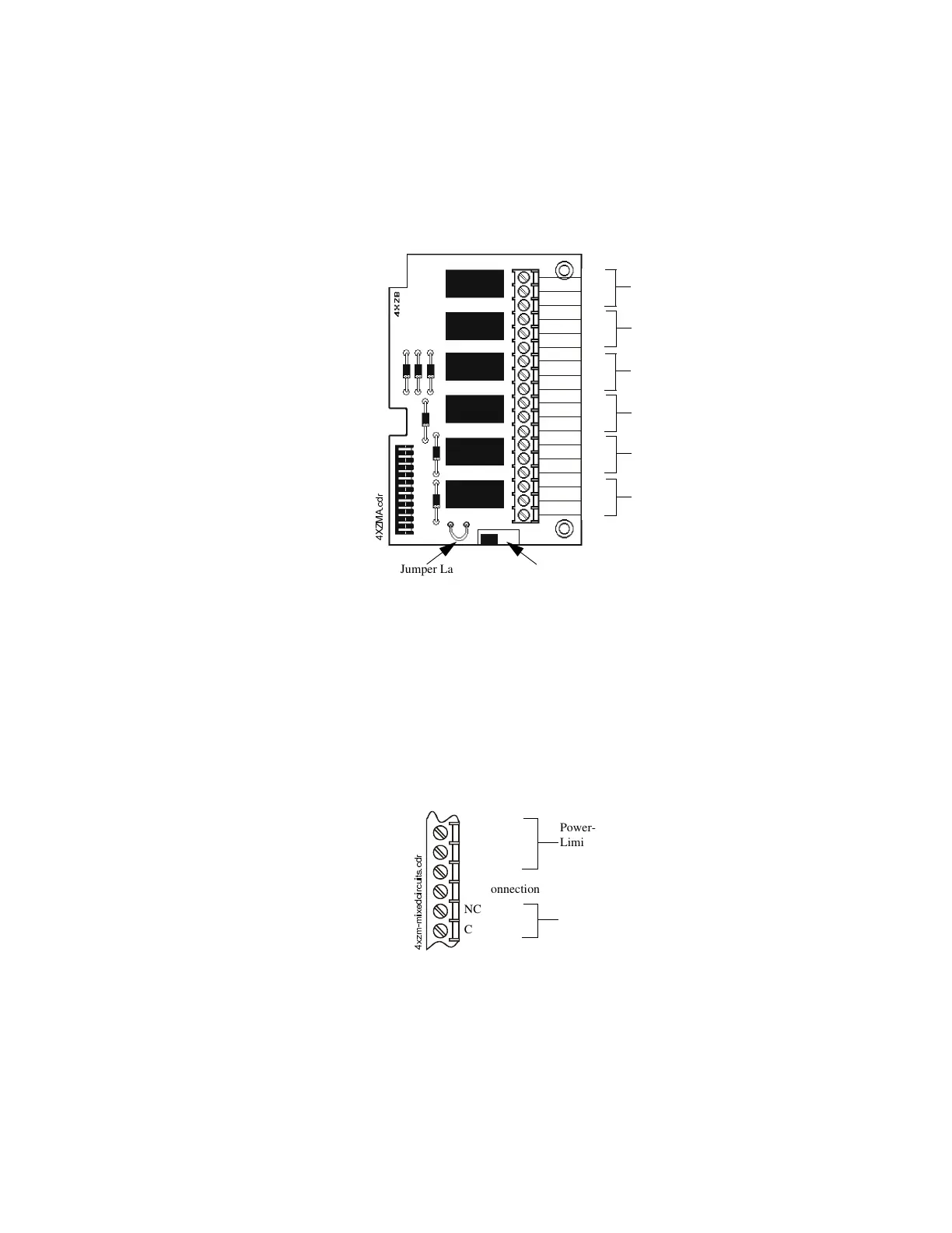
=RQH5HOD\0RGXOH²;=0
Relays #1 through #4 on this module have specific functions based on the configuration of DIP
switches SW1-1 and SW1-2 on the control panel. See “Setting Mode of Operation” in Section 2.10
for a more detailed explanation of the conditions that will activate each relay under the different
DIP switch settings.
For non-latching (silenceable) relay operation, cut the jumper “LATCH” (see Figure 2.10). To
disconnect relays entirely, slide the disable switch to the right.
The wiring of this module must follow the requirements specified under “UL Power-limited Wiring
Requirements” in Section 2.2. Non-power-limited and power-limited wiring must have a minimum
distance of 0.25 in. (6.35 mm) wire to wire.
• If this module is used to drive both non-power-limited and power-limited circuits, skip one
terminal of a set of dry contacts to maintain the required separation between circuit types.
• If this module is needed to drive both power-limited and non-power-limited relays that are
next to each other, refer to Figure 2.11 showing one allowable arrangement.
Note: If any dry contacts are to be used as non-power-limited circuits, write this on the Protected
Premises Unit label, located on the door of the control panel.
Figure 2.10 Wiring the Zone Relay Module
NO
NC
C
NO
NC
C
NO
NC
C
NO
NC
C
NO
NC
C
NO
NC
C
Relay #1
Relay #2
Relay #3
Relay #4
Alarm
Trouble
Disable Switch
;=0$FGU
Jumper Latch
Figure 2.11 Mixing Power-Limited and Non-Power-Limited Circuits
[]PPL[HGFLUFXLWVFGU
NO
NC
C
No Connection
NC
C
Power-
Limited
Circuit
Non-Power-
Limited Circuit
 Loading...
