PAGE 5
FRONT PANEL INDICATORS (Continued)
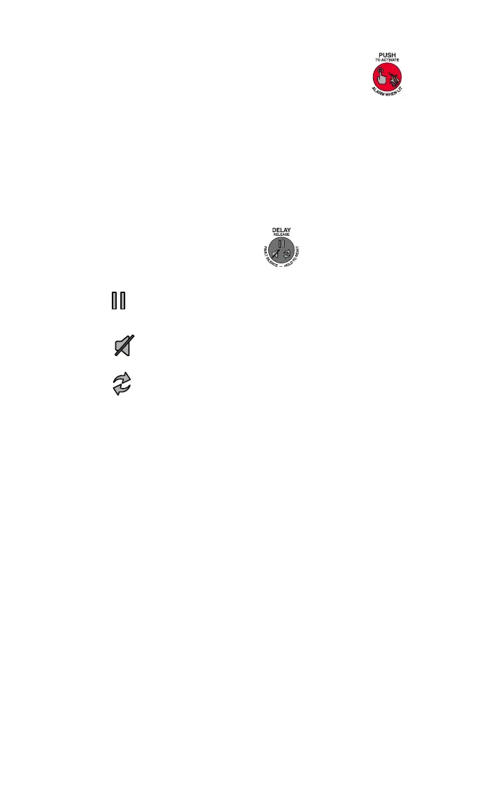
3) Red “PUSH” To Activate / Alarm When Lit” LED
(sounder matches pulse rate).
a. Pulsing 2 x 1 sec. indicates Alarm Condition and time
delay starts countdown (last 5 sec. pulsing increases to
4 x 1 sec.).
b. Steady-on for 10 sec. indicates Release Activated.
c. Pulsing 1 x 10 sec. indicates Post Release Activated.
d. LED is also a button, see page 2 for manual activation of
fire suppression system.
4) DELAY/Reset/Silence Button
a. Icons on button represent options for system control.
During Time Delay, press button to restart Time
Delay.
When sounder is pulsing, press button to silence.
Press and hold button for 3 sec. to reset system.

 Loading...
