TOTAL INERGEN QTY. (CU. FT.): (From Page 1)
CYLINDER REQUIREMENTS: TOTAL CYLINDER CAPACITY:
(Total INERGEN qty. ÷ Cylinder Capacity rounded to next highest whole number) (Cyl. qty. x Cyl. cap.)
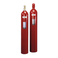
572 cu. ft. Cylinders:
CYLINDER SIZE SELECTED: (Cylinder qty. x Cylinder capacity)
INERGEN AGENT SUPPLIED:
ACTUAL INERGEN AGENT PER AREA:
[(Actual INERGEN Qty. ÷ Total INERGEN Qty.) x INERGEN Agent Supplied]
ACTUAL INERGEN FLOODING FACTOR:
[(Actual INERGEN Agent per Area ÷ Alt. Correction Factor) ÷ Total Reduced Volume]
CONCENTRATION RANGE CHECK:
(Design Conc. Must be Between 34.2% – 52% For Occupied Spaces)
Room Max. Ambient Temp.:
Design Concentration at Max.Temp.:
(Locate Actual INERGEN Conc. at Max. Temp. on Table, or Use Calc. in Design Manual)
DISCHARGE TIME:
Normal Ambient Temperature:
Design Concentration at Ambient Temp.:
(Locate Actual INERGEN Conc. at Ambient Temp. on Table, or Use Calc. in Design Manual)
90% of Agent Discharge Time (Sec.):
(Time From Table in Design Manual)
90% of Agent Discharge Time (Min.):
(Discharge Time (Sec.) ÷ 60)
ESTIMATED FLOW RATES
Estimated System Flow Rate: [(INERGEN Agent Supplied x .9) ÷ 90% Discharge Time (Min.)]
Estimated Pressure Reducer Pipe Size: (Refer to Pipe Sizing Chart)
Nozzle Quantity:
[Length ÷ 32 (Rounded to Next Highest Whole Number) x Width ÷ 32 (Rounded to Next Highest Whole Number)]
Estimated Nozzle Flow Rate:
[((Actual INERGEN Agent Per Area x .9) ÷ 90% Discharge Time (Min.)) ÷ Nozzle Quantity]
Estimated Nozzle Pipe Size:
Pipe Length Factor (S = Short, L = Long):
Pipe Size:
(Refer to Pipe Sizing Chart)
ANSUL and INERGEN are trademarks of Ansul Incorporated or its affiliates.
ANSUL INCORPORATED, ONE STANTON STREET, MARINETTE, WI 54143-2542 715-735-7411 Form No. F-2001293 © 2001 Ansul Incorporated Litho in U.S.A.
INERGEN® SYSTEM DESIGN CALCULATION WORKSHEET (Continued)


 To Next Page
 Loading...