7
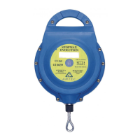
- BLOCMAX EN353-2 rope grab moun-
ted on SFPF 1010441 flexible vertical
support (kernmantel Ø11mm) and
SFPF 1009287 (3T rope Ø14mm).
It is used for safely ascending and
descending building facades, fra-
meworks, roofs, towers etc. In the
event of fall, it will lock instantly on
the support.
In the same way, the work positio-
ning system is designed for use with
a mobile fall arrester (cf. EN353-2 for
flexible work positioning supports
(ropes, etc. …) or cf. EN353-1 for ri-
gid work positioning supports (cable,
etc. …) of the same BRAND.
For EN353-1 systems:
- The user’s weight, attire and equip-
ment included, must not exceed the
maximum test weight selected (See
marking).
- The rope grab can be used up to a
minimum temperature of -30°C.
CONNECTION
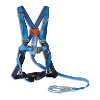
The slide must be used with a fall ar-
rest harness (cf. EN 361). It must never
be used with a work positioning sys-
tem (belts). It must be connected to
the harness EXCLUSIVELY using the
connector suppliedor an equivalent
part. The length of the part linking
up the fall arrest rope grab and the
harness must not be modified (e.g.
never add a miniature lanyard or re-
move the dissipator from the original
linking part).
The mobile fall protection connection
to the harness must not be made on
the sternal points which have been
tested for this purpose (front fall ar-
rest point) so as to prevent any risk of
shifting to a head downward position
when arresting the fall. The ventral
and/or sternal straps of the harness
must be adjusted as close as to the
body as possible to prevent any ex-
cess slack (do not use the product
when the size of the harness does
not permit this adjustment). For the
EN353-2 systems using a rope, a dor-
sal fall arrest connection is authorized.
NEVER ADD AN ADDITIONAL LIN
KING ELEMENT BETWEEN THE
SLIDE AND THE HARNESS
INSTALLATION
EN353-2 systems:
Attach the end of the anchorage sup-
port (rope or cable) to the anchorage
point using a connector in conformity
with standard (EN 362). Only the re-
commended diameter and type of
work positioning support are to be
used. If possible, weight the other end
of the anchorage support.
EN353-1 systems:
For the EN353-1 cable systems, opti-
mal operation can be obtained when
the recommended tensioning is ap-
plied in the lifeline (60daN).All the
information needed for installation of
the system is explained in detail in the
installation guide
If it becomes necessary to open the
slide so as to fit it to the support, ope-
rate as shown by the diagrams concer-
ning your fall arrester. In addition, for
units with two operating positions
(slide/lock), and to prevent any risk
of disturbing the brake system in the
ascent or descent, all handling ope-
rations to change the configuration
must be made in a safe position (wi-
thout any risk of falling).
Only the recommended Ø and type
of belay system can be used. (See the
paragraph on use or the installation
guide)
Important recommendations :
When a manual fall arrester (or a fall
arrester in the manual position) is
being used, the bottom end of the
rope must be attached or heavily
weighted. Check the compatibility of
the fall arrester with the anchorage
support.
CHECKING BEFORE USE
Before each use, carry out a tho-
rough visual examination to ensure
that thePPE, as well as any other
equipment with which it could be
associated (connector, lanyard…) is
complete. Make all necessary arrange-
ments for the implementation of any
rescue in total safety. In the event of
your product being damaged, consult
the manufacturer or his agent. If you
have any doubts regarding the safe
GB
NT90008818 IND E.indd 7 22.8.2011 13:07