APW9 Power Supply Maintenance Guide
9
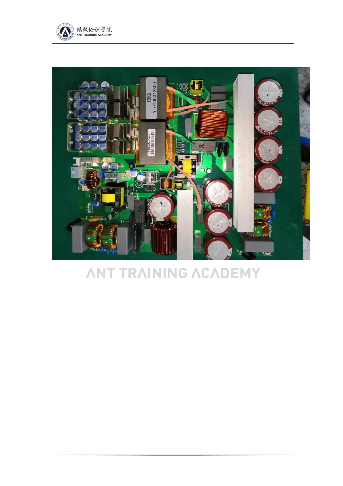
2A-- second AC input and EMI circuit, 2B-- PFC and main shunt MOS circuit, 2C-- 12V
auxiliary and VCC circuit, 2D- 12V output port and PIC communication port
Physical picture, there will be small differences in product versions, but the principle is
similar.
2.21 Two AC input EMI to PFC circuit schematic diagram, such as AC 1 key measure F1
insurance, U2 rectifier bridge, whether there is any damage in Q4, D7, D5, D6 (the other
check method is the same). Note that if MOS is damaged, the drive resistance and circuit may
be damaged synchronously and need to be replaced. During normal operation, it can be
judged that the DC voltage at both ends of the large capacitor is 410-420v.
 Loading...