Do you have a question about the Anton Paar DHS 1100 and is the answer not in the manual?
Covers liability, installation, use, maintenance, disposal, and precautions for flammable materials.
Explains the meaning of WARNING, CAUTION, NOTICE, and symbols used in the manual.
Shows warning symbols on the instrument and advises to keep them legible.
Details the DHS 1100 Domed Hot Stage, its design, applications, and required accessories.
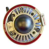
Describes the components of the DHS 1100, including housing, cooling ring, and domes.
Explains the graphite and PEEK dome materials, their properties, and applications.
Provides information on the cooling nozzle for PEEK dome operation.
Details the housing material, cooling fins, heating plate, springs, and internal components.
Describes the connection device for gas/vacuum and temperature control.
Explains the function and operation of the CCU 100 for sample plate temperature control.
Details the control buttons, status LEDs, and display on the CCU 100 front panel.
Lists and describes the connectors found on the CCU 100 rear panel.
Explains how the CCU 100 controls the compressed-air cooling system.
Describes the protective thermoswitch and overheat protection mechanism.
Recommends the Air Service Unit for compressed air requirements.
Lists requirements for X-ray diffractometer, electrical, compressed-air, and vacuum equipment.
Provides instructions and warnings for carefully unpacking the instrument.
Details how to mount the DHS 1100 to the goniometer using bore holes and quick coupling.
Explains installing compressed air cooling, connecting it to CCU 100 and Air Service Unit.
Describes connecting gas/vacuum hoses for operation under vacuum or inert gas.
Guides on rack mounting the CCU 100 and ensuring adequate space and ventilation.
Explains connecting the CCU 100 to a computer via RS 232 for remote control.
Details specifications for PEEK dome operation, including cooling nozzles.
Describes standard alignment at room temperature and potential adjustments for accurate measurements.
Provides step-by-step instructions for powering on and initializing the CCU 100.
Details the CCU 100's front panel layout: keypad, LEDs, and display.
Details the CCU 100 keypad functions and status LEDs.
Explains the CCU 100 display elements and its navigation diagram.
Lists and describes CCU 100 parameters like heating/cooling rate and dome configuration.
Details configurable CCU 100 parameters like heating rate activation and set point range.
Explains how to turn the CCU 100 heater on and off.
Describes the two modes (cOFF, CON) for controlling compressed-air cooling.
Guides on manual operation for setting sample temperature and heating/cooling rate.
Discusses remote control options via diffractometer software or NAMBICON software.
Outlines safety requirements and conditions for operating the DHS 1100.
Details the process of mounting flat samples onto the heating plate.
Provides step-by-step instructions for mounting and removing the dome.
Details specific requirements for operating with a PEEK dome, including cooling nozzles.
Guides on starting measurements after sample mounting and alignment.
Lists and describes alarm messages (E01-E13, E98-E99) and their causes.
Explains general messages like '8888' and '9999' shown on the CCU 100 display.
Refers to the reference manual for detailed error analysis.
Outlines regular checks for the dome, including cracks and coatings.
Describes replacing O-rings, emphasizing careful handling of sealing surfaces.
Details the procedure for removing and replacing the hot plate.
Covers switching off the instrument and checking/replacing main fuses.
Lists parts excluded from warranty and additional exclusions for damage.
Explains how to contact representatives for repairs and required documentation.
Lists temperature ranges for Graphite Dome and PEEK Dome under various atmospheres.
Specifies permitted gases and pressure limits for the dome.
Details the temperature control unit, sensor type, and heater type.
Provides physical dimensions and weight of the DHS 1100.
Lists sample plate diameter, thickness, height, and fixing method.
Details dome diameter, wall thickness, X-ray transmission, and angular range.
Specifies cooling air pressure and flow rate for different dome configurations.
Enumerates materials used for sample plate, springs, thermocouple, heater, dome, housing, etc.
Provides dimensions and weight of the CCU 100.
Details voltage, frequency, power consumption, fuses, and output parameters for CCU 100.
Specifies ambient temperature, humidity, pollution degree, and operating altitude.
General advice on instrument disposal.
Lists CE compliance directives and applied standards for EMC and Low Voltage.
Official declaration by Anton Paar GmbH regarding product conformity to EU legislation.
| Control System | Digital PID controller |
|---|---|
| Temperature stability | ±0.1 °C |
| Power Supply | 50/60 Hz |
| Cooling Technology | Not applicable |
| Cooling | Not applicable |
| Display | LCD |
| Interface | RS-232 |